
Thin-film getter with high gas absorption performance and preparation method thereof

A getter and film technology, applied in the field of new vacuum acquisition and maintenance materials and its preparation, can solve the problems of poor film adhesion, low preparation efficiency, and high preparation cost, and achieve increased adhesion, inhibition of poisoning, and high absorption The effect of gas performance

Active Publication Date: 2013-07-03
GRIMAT ENG INST CO LTD
View PDF5 Cites 24 Cited by
  • Summary
  • Abstract
  • Description
  • Claims
  • Application Information

AI Technical Summary

Problems solved by technology

[0004] At present, there are many deficiencies in the material system and preparation method of thin film getters, and the outstanding problems are: (1) V is contained in most non-evaporable systems such as Ti-Zr-V, and its toxicity is very harmful to the human body. At the same time, Ti -Zr-V alloy target is difficult to smelt and process, and the preparation cost is high
(2) The thin-film getter prepared by DC magnetron sputtering usually uses a very low deposition rate (1-8nm / min), and the deposition time is as long as more than 10 hours, which is difficult to meet the needs of industrialized high-efficiency production; (3) protection Layer and low-temperature activation layer process is complicated, which may reduce the specific surface area of ​​the film and increase the gas diffusion resistance; (4) The problem of poor adhesion of the film on some substrates has not been solved; (5) The vacuum degree of the back when preparing the film Usually choose 10 -6 Pa level, the requirements for the configuration of the vacuum system of the equipment are too high; (6) The substrate or the device shell needs to be baked and degassed for more than ten hours before depositing the thin film getter, otherwise it will Gas diffuses directly to the active host layer, resulting in loss of film getter properties (poisoning effect)
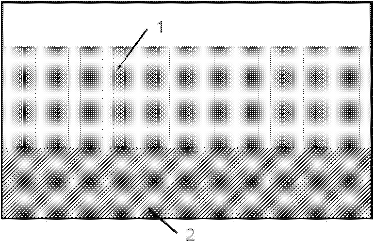
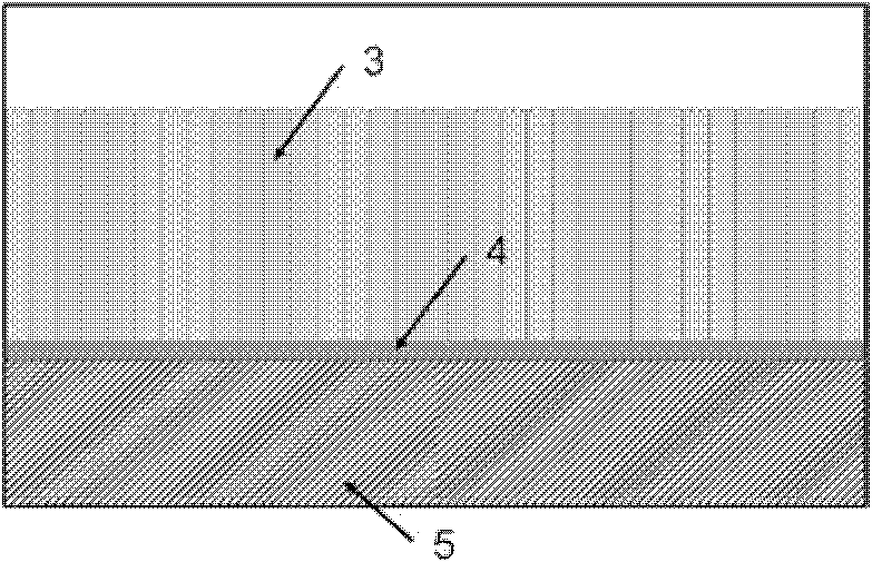
[0005] The innovation of the present invention lies in the use of a new material system that does not contain V, and the use of radio frequency magnetron sputtering to efficiently prepare thin film getters, and at the same time prepare nano-scale porous columnar structures by adjusting process parameters and introducing adjustment layers , effectively solved the problems of low preparation efficiency, easy poisoning, and poor adhesion, reduced the baking and degassing time of the substrate, shortened the process flow, and provided a valuable solution for the large-scale application of thin film getters. At present, there is no institution in China to use this method to prepare a similar high-performance thin-film getter.

Method used


Image

  • Thin-film getter with high gas absorption performance and preparation method thereof
  • Thin-film getter with high gas absorption performance and preparation method thereof
  • Thin-film getter with high gas absorption performance and preparation method thereof

Examples


Embodiment 1

[0060] Prepare a borosilicate glass substrate of a certain size according to the actual requirements of the equipment or device, with an area of ​​0.01-100cm 2 Between, the surface roughness Ra2 SO 4 :H 2 o 2 :H 2 Soak in a solution of O (18:1:1) for 10 minutes, rinse with a large amount of deionized water for 3 minutes after taking it out, and air-dry it for later use. Using radio frequency magnetron sputtering method, the target material is a multi-element alloy 70wt% Zr-25wt% Co-5wt% RE, where RE is Y 20 La 30 Ce 10 PR 40 (wt%), the purity is 99.7wt%. First vacuum the coating system to 8×10 -5 Pa, and then introduce argon gas with a volume fraction of 99.99%, and maintain the argon pressure at about 3.5Pa. First, pre-sputter to clean the surface of the target for 20 minutes, and then adjust the relevant deposition parameters to start preparing the getter absorption layer. The parameters are: : The RF power is 100W, the distance between the target and the substrate ...

Embodiment 2

[0062]The operation method and process conditions are basically the same as in Example 1, the only difference is that the target is a multi-element alloy 80wt%Zr-16wt%Co-4wt%RE, where RE is Y 20 La 30 Ce 10 PR 40 (wt%), the target purity is 99.7wt%. Under this condition, the average thickness of the gas absorbing layer is 3.2 μm, the fiber diameter is about 1-10 nm, and the diameter of the columnar structure is about 100-200 nm.

Embodiment 3

[0064] The operation method and process conditions are basically the same as those in Example 1, the only difference lies in the preparation of a gas-absorbing layer and regulating layer double-layer film, that is, depositing a layer of regulating layer first, and then preparing the gas-absorbing layer. Adjustment layer deposition parameters: RF power 120W, distance between target and substrate 4cm, working pressure 0.2Pa, deposition time 3min, substrate spin speed 20r / min; gas absorption layer deposition parameters are the same as in Example 1. Under this condition, the average thickness of the adjustment layer is 165 nm, the average thickness of the gas absorption layer is 3.2 μm, the fiber diameter is about 1-10 nm, and the diameter of the columnar structure is about 100-200 nm. Its inspiratory performance is as Figure 6 Shown in curve 1.


PUM

PropertyMeasurementUnit
diameteraaaaaaaaaa
lengthaaaaaaaaaa
diameteraaaaaaaaaa

Abstract

The invention provides a thin-film getter with high gas absorption performance and a preparation method thereof. The thin-film getter is formed by depositing a gas absorbing layer on a metal, silicon, ceramic or glass substrate or on the inner wall of a sealed device or is a film with two-layer structure composed by the gas absorbing layer and an adjusting layer, wherein the gas absorbing layer is multi-component alloy formed by Zr, Co and at least one material selected from the group consisting of Y, La, Ce, Pr and Nd, and the adjusting layer is one or alloy of more selected from the group consisting of Ti, Zr, Y, Hf, Mn, Cu, Cr, Al, Fe, Pt and Ru. The preparation method employs radio frequency magnetron sputtering for deposition of films of the gas absorbing layer and the adjusting layer. The thin-film getter provided by the invention is activated at a temperature in a range of 250 to 350 DEG C, has a high gas absorption rate and high gas absorption capacity, overcomes the problems of poor adhesion, low preparation efficiency and easy poisoning during activation of conventional thin-film getters and can meet design requirements for a vacuum working environment needed for realizing high reliability and a long service life of micro-electromechanical systems (MEMS), flat-panel displays (OLED / FED / LCD), solar heat-insulating boards and hydrogen-sensitive microelectronic devices.

Description

technical field [0001] The invention belongs to a novel vacuum obtaining and maintaining material and a preparation method thereof. Specifically, the present invention relates to a thin-film getter with high gettering performance and a method for preparing the thin-film getter on the inner wall of a substrate or a sealed device. Background technique [0002] The getter material can absorb the residual active gas in the vacuum device or the active gas released during the use of the device through physical or chemical adsorption, improve the ultimate vacuum level of the vacuum system, avoid the decline of the vacuum quality with the service life, and reduce the activity. Vibration damping of components, reduction of heat dissipation in the inner cavity, avoiding pollution or quality changes caused by the reaction of gas and precision components, to achieve the purpose of maintaining the vacuum quality and ideal working environment of vacuum equipment or sealed devices. Getter...

Claims


Application Information

Patent Timeline
Patent Type & Authority Applications(China)
IPC IPC(8): B01J20/28B01J20/30B01D53/04
Inventor 毛昌辉卜继国张艳张心强
Owner GRIMAT ENG INST CO LTD
Learn More