Multiphase non-overlapping clock circuit

A clock circuit, non-overlapping technology, applied in the field of multi-phase clock processing circuits, can solve problems such as burning out the power supply and inaccurate calculation results, and achieve the effects of high reliability, simple structure and low cost

Active Publication Date: 2013-06-19
江苏芯力特电子科技有限公司
View PDF6 Cites 10 Cited by
  • Summary
  • Abstract
  • Description
  • Claims
  • Application Information

AI Technical Summary

Problems solved by technology

In this way, the circuit calculation results may be

Method used


Image

  • Multiphase non-overlapping clock circuit
  • Multiphase non-overlapping clock circuit
  • Multiphase non-overlapping clock circuit

Examples


Embodiment 2

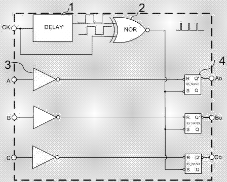
[0020] Example two image 3 As shown, it includes a delay module 1, a periodic pulse generating module 2, a plurality of inverters 3 and a plurality of RS flip-flops 4. The periodic pulse generating module 2 is a two-input exclusive OR gate, and each flip-flop 4 is two The basic RS flip-flop composed of NAND gates, each inverter 3 has the same structure, the input terminal of the delay module 1 is connected to one of the input terminals of the periodic pulse generating module 2, and the output terminal of the delay module 1 is connected to the periodic pulse generating module The other input terminal of 2; the output terminal of the periodic pulse generating module 2 is connected to the set terminal of each RS flip-flop 4, and the input terminal of each inverter 3 is used as the input port of the multiphase clock. The output terminals are respectively connected to the reset terminals of each RS flip-flop 4, and the output terminals of each RS flip-flop 4 are respectively used as...


PUM


Abstract

The invention discloses a multiphase non-overlapping clock circuit which comprises a delay module, a recurrent pulse generation module, a plurality of inverters and a plurality of RS triggers. The input end of the delay module is connected with one input end of the recurrent pulse generation module to serve as an input port of a mater clock. The output end of the delay module is connected to the other input end of the recurrent pulse generation module. The output end of the recurrent pulse generation module is connected to the setting ends of the RS triggers. The input ends of the inverters respectively serve as the input ports of a multiphase clock. The output ends of the inverters are respectively connected to the other input ends of the corresponding RS triggers. The output ends of the RS triggers respectively serve as the output ends of the multiphase non-overlapping clock. The multiphase non-overlapping clock circuit is simple in structure, small in occupied area of a chip, and high in reliability. By means of the circuit, processing can be carried out on the multiphase clock synchronous with the master clock.

Description

technical field [0001] The invention relates to a multiphase clock processing circuit, in particular to a multiphase non-overlapping clock circuit. Background technique [0002] With the continuous improvement of integrated circuit design technology, people require more and more accurate calculation results of integrated circuits, thus requiring more and more accurate control circuits. In the circuit, the same node can establish signal paths with other multiple signal sources through multiple switches. These signal sources may be different nodes in the circuit, or different power supplies. The control circuit must generate certain switching signals to control the connection between the node and the signal source. Other signal sources are connected in an orderly manner. Generally, the switching signals generated by the control circuit can basically make the node connect to other signal sources in time division. The clock is synchronized, so the rising and falling edges of d...

Claims


Application Information

Patent Timeline
IPC IPC(8): H03K3/78H03K5/00
Inventor 张文杰谢亮金湘亮
Owner 江苏芯力特电子科技有限公司
Why Eureka
Try Eureka