
Macro-micro compound five free degree light-emitting diode (LED) bonding machine actuating mechanism

A technology with actuators and degrees of freedom, applied in the field of wire bonding machines, can solve problems such as poor LED welding consistency, position deviation, and long time, and achieve the effects of meeting precision requirements, increasing yield, and short adjustment time

Inactive Publication Date: 2013-05-08
GUANGDONG UNIV OF TECH
View PDF7 Cites 8 Cited by
  • Summary
  • Abstract
  • Description
  • Claims
  • Application Information

AI Technical Summary

Problems solved by technology

[0003] The current problem with the wire bonding machine is that in principle, the rivet and the LED array must be perpendicular to the workbench to ensure the consistency of the quality of the solder joints. However, the current situation is that due to processing, assembly, etc. If it is not vertical, the soldering consistency of the LEDs is not good. Some LEDs can be soldered, and some will have positional deviations and lead to waste products.
The current solution is to improve the processing and assembly precision, generally by manually adjusting the angle of the riving knife to make it as vertical as possible to the workbench, then try welding, and then debug, so as to achieve the desired effect repeatedly, but such a process is mainly Repeated debugging by naked eyes and manual, long time, low precision, unstable

Method used


Image

  • Macro-micro compound five free degree light-emitting diode (LED) bonding machine actuating mechanism
  • Macro-micro compound five free degree light-emitting diode (LED) bonding machine actuating mechanism
  • Macro-micro compound five free degree light-emitting diode (LED) bonding machine actuating mechanism

Examples


Embodiment Construction

[0027] The technical solutions in the embodiments of the present invention will be clearly and completely described below in conjunction with the accompanying drawings in the embodiments of the present invention. Obviously, the described embodiments are only a part of the embodiments of the present invention, rather than all the embodiments. Based on the embodiments of the present invention, all other embodiments obtained by those of ordinary skill in the art without creative work shall fall within the protection scope of the present invention.

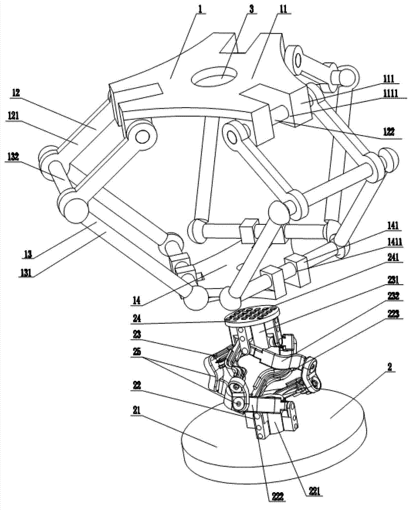
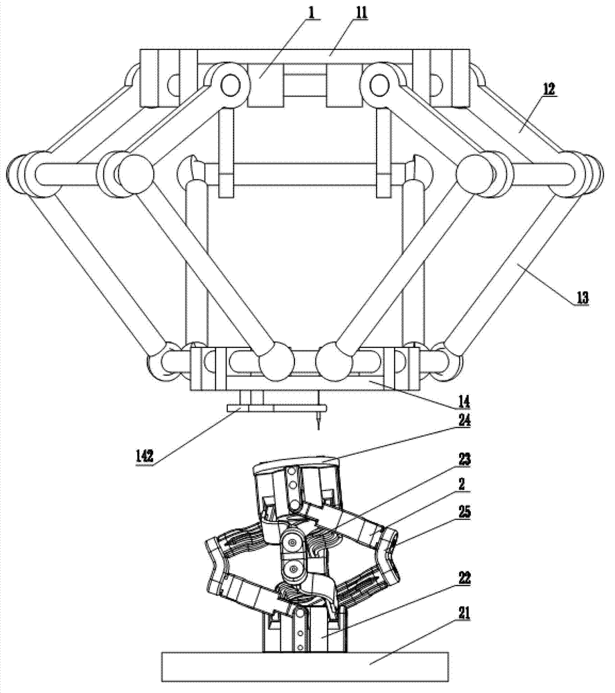
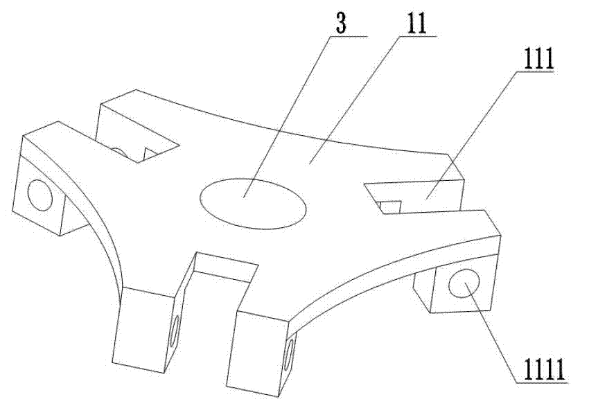
[0028] according to Figure 1-Figure 6 In the preferred embodiment shown, a macro-micro composite five-degree-of-freedom LED wire bonding machine actuator includes a welding head mechanism 1, a worktable mechanism 2 connected to the welding head mechanism 1, and the welding head mechanism 1 includes an upper substrate 11, and The driving component 12 connected to the upper substrate 11, the driven component 13 connected to the driving com...


PUM


Abstract

The invention provides a macro-micro compound five free degree light-emitting diode (LED) bonding machine actuating mechanism which comprises a welding head mechanism and an operating platform mechanism which is connected with the welding head mechanism. The operating platform comprises a lower baseplate, a first component which is connected with the lower baseplate, a second component which is connected with the first component and a material platform which is connected with the second component. The first component and the second component are connected through a double revolute pair. The first component comprises a lower base, first driving arms and first driven arms. The first driving arms and the first driven arms are arranged on the outer side of the lower base. The second component comprises an upper base and a connecting rod which is arranged on the outer side of the upper base. The first driving arms and the first driven arms are connected respectively through the double revolute pair and the connecting rod. On one hand, the welding head mechanism can achieve moving with high speed and high acceleration and meets accuracy requirements, and on the other hand, a micro transmission mechanism can ensure perpendicularity between a chopper and a welding plane, and therefore motion control and force control of a welding mechanism of the whole bonding machine is enabled to be more stable, and the welding quality is better.

Description

Technical field [0001] The invention relates to the field of wire bonding machines, in particular to a macro-micro composite five-degree-of-freedom LED wire bonding machine actuator. Background technique [0002] Compared with the currently widely used series robots, parallel robots have significant advantages such as strong rigidity, high precision, low weight-to-load ratio, and high speed. There are many kinds of parallel robot mechanisms. Clavel proposed a three-dimensional moving mechanism called Delta , Delta mechanism is the most typical spatial three-degree-of-freedom parallel mechanism is derived from Delta mechanism. Delta robot is a high-speed parallel robot with 3 translational degrees of freedom, and it is also one of the most successful parallel robots in commercial applications. Due to the existence of a spatial parallelogram in the mechanism, the three rotational degrees of freedom of the mechanism are restricted, leaving only three translational degrees of freedo...

Claims


Application Information

Patent Timeline
Patent Type & Authority Applications(China)
IPC IPC(8): B25J9/00B23K20/10
Inventor 刘冠峰吴上伟陈新李泽湘高健
Owner GUANGDONG UNIV OF TECH
Learn More