
Multilayer ceramic capacitor and preparation method thereof

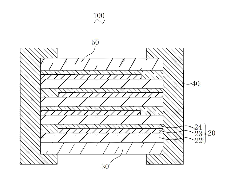
A technology of multilayer ceramics and capacitors, applied in the direction of multilayer capacitors, fixed capacitor electrodes, fixed capacitor dielectrics, etc., can solve the short circuit of the inner electrode layer, reduce the contact area of ​​the ceramic dielectric layer, and reduce the facing between the inner electrode layers. Area and other issues, to eliminate height differences and voids, ensure the facing area, and achieve the effect of high effective capacity

Active Publication Date: 2013-04-17
GUANGDONG FENGHUA ADVANCED TECH HLDG
View PDF5 Cites 15 Cited by
  • Summary
  • Abstract
  • Description
  • Claims
  • Application Information

AI Technical Summary

Problems solved by technology

[0003] Due to the existence of the height difference, during the preparation process, when the ceramic dielectric layer and the internal electrode layer are stacked alternately, the pressure applied to the laminated structure composed of the ceramic dielectric layer and the internal electrode layer will cause the ceramic dielectric layer to be easily torn. problem, resulting in a short circuit between the inner electrode layers of different polarities of adjacent layers
Due to the existence of voids, it is easy to cause partial layers in the ceramic body during sintering, and reduce the contact area of ​​adjacent ceramic dielectric layers, so that when pressure is applied to the laminated structure, the adhesion between the upper ceramic dielectric layer and the lower internal electrode layer Insufficient resultant force increases the tendency of unwanted relative displacement between adjacent ceramic dielectric layers, which reduces the facing area between internal electrode layers, resulting in a decrease in the effective capacity of multilayer ceramic capacitors

Method used


Image

  • Multilayer ceramic capacitor and preparation method thereof
  • Multilayer ceramic capacitor and preparation method thereof
  • Multilayer ceramic capacitor and preparation method thereof

Examples


preparation example Construction

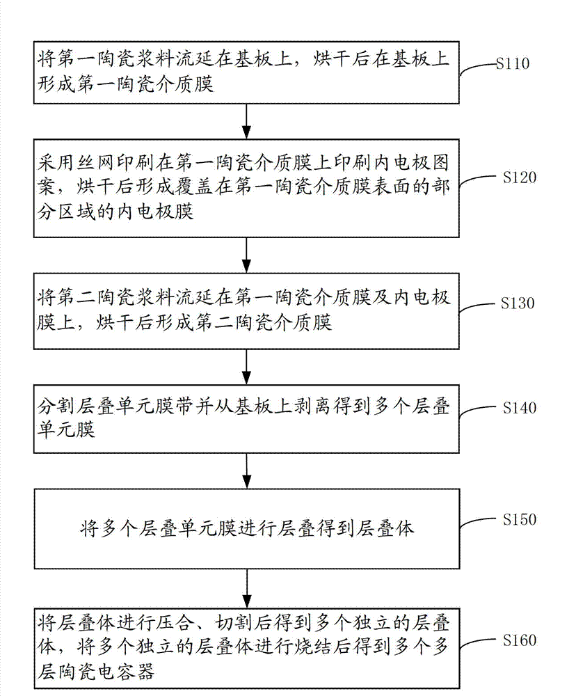
[0046] see image 3 , the preparation method of the multilayer ceramic capacitor of an embodiment, comprises the steps:

[0047] Step S110: casting the first ceramic slurry on the substrate, and forming a first ceramic dielectric film on the substrate after drying.

[0048] Please also refer to FIG. 4( a ), the substrate 210 is a polyethylene terephthalate (PET) substrate, so as to facilitate subsequent peeling and avoid damage to the first ceramic dielectric film 220 during peeling.

[0049] The first ceramic slurry includes 45-50% by mass of ceramic powder, 15-20% by mass of organic binder and 30-40% by mass of solvent.

[0050] The main component of the ceramic powder is preferably barium titanate, the organic binder is preferably polyvinyl butyral, the solvent is preferably a mixture of toluene and ethanol, and the mass ratio of toluene and ethanol is 1:1~4:1.

[0051] The ceramic powder, the organic binder and the solvent are mixed according to the above mass percentage...

Embodiment 1

[0089] 1. Mix 45% by mass of ceramic powder, 15% by mass of organic binder and 40% by mass of solvent to obtain a first ceramic slurry with a viscosity of 300 cps. Among them, the main component of the ceramic powder is barium titanate, the organic binder is polyvinyl butyral, and the solvent is a mixture of toluene and ethanol at a mass ratio of 1:1. Casting and coating the first ceramic slurry on the PET substrate with a tape casting machine to form a first ceramic slurry layer, and then drying at 60° C. to form a first ceramic dielectric film with a thickness of 0.8 microns;

[0090] 2. Print the internal electrode layer pattern on the above-mentioned first ceramic dielectric film by screen printing, and then dry it at 70°C to form an internal electrode film with a thickness of 1 micron covering a part of the surface of the first ceramic dielectric film And the alignment mark, the inner electrode film is nickel electrode film;

[0091] 3. Mix 45% by mass of ceramic powder,...

Embodiment 2

[0098] 1. Mix 50% by mass of ceramic powder, 20% by mass of organic binder and 30% by mass of solvent to obtain a first ceramic slurry with a viscosity of 450 cps. Among them, the main component of the ceramic powder is barium titanate, the organic binder is polyvinyl butyral, and the solvent is a mixture of toluene and ethanol at a mass ratio of 4:1. Casting and coating the first ceramic slurry on the PET substrate with a tape casting machine to form a first ceramic slurry layer, and then drying at 70° C. to form a first ceramic dielectric film with a thickness of 4 microns;

[0099] 2. Print the internal electrode layer pattern on the above-mentioned first ceramic dielectric film by screen printing, and then dry it at 80°C to form an internal electrode film with a thickness of 1.5 microns covering a part of the surface of the first ceramic dielectric film And the alignment mark, the inner electrode film is nickel electrode film;

[0100] 3. Mix 50% by mass of ceramic powder...


PUM

PropertyMeasurementUnit
thicknessaaaaaaaaaa
thicknessaaaaaaaaaa
thicknessaaaaaaaaaa

Abstract

The invention provides a multilayer ceramic capacitor, which comprises a plurality of superposed superposing units, wherein each superposing unit comprises a first ceramic dielectric layer and an inner electrode layer formed in a partial area on the surface of the first ceramic dielectric layer; each superposing unit also comprises a second ceramic dielectric layer which covers the inner electrode layer and an area which is not covered by the inner electrode layer on the surface of the first ceramic dielectric layer; and a distance from the surface of the second ceramic dielectric layer far from the first ceramic dielectric layer to the surface of the inner electrode layer far from the first ceramic dielectric layer is 0.56 to 2.1 micrometers. By the multilayer ceramic capacitor with the structure, height difference and gaps are eliminated, inner electrode layers of two adjacent superposing units can be accurately aligned, and the reliability and effective capacity of the multilayer ceramic capacitor are higher. Furthermore, the invention provides a preparation method for the multilayer ceramic capacitor.

Description

technical field [0001] The invention relates to the field of electronic components, in particular to a multilayer ceramic capacitor and a preparation method thereof. Background technique [0002] Multilayer Ceramic Capacitor (MLCC) is one of the most widely used electronic components. The ceramic body of a conventional multilayer ceramic capacitor generally includes a plurality of ceramic dielectric layers and internal electrode layers alternately laminated with multiple ceramic dielectric layers. The ceramic dielectric layers and internal electrode layers are alternately laminated in sequence. Since the internal electrode layer has a certain thickness, And the internal electrode layer does not completely cover the surface of the ceramic dielectric layer, so that the surface of the ceramic dielectric layer provided with the internal electrode layer forms a height difference, and no internal electrode layer is stacked on the ceramic dielectric layer between adjacent ceramic d...

Claims


Application Information

Patent Timeline
Patent Type & Authority Applications(China)
IPC IPC(8): H01G4/005H01G4/12H01G4/30
CPCH01G4/012H01G4/12H01G4/255H01G4/30
Inventor 宋子峰祝忠勇韦豪任周锋陆亨
Owner GUANGDONG FENGHUA ADVANCED TECH HLDG
Learn More