
Method for preparing high-efficiency membrane electrode of direct methanol fuel cell

A methanol fuel cell, high-efficiency membrane technology, applied in battery electrodes, circuits, electrical components, etc., can solve the problems of difficulty in ensuring the consistency of membrane electrode performance, complex membrane electrode preparation process, and difficulty in establishing proton channels.

Inactive Publication Date: 2013-03-27
UNIV OF SCI & TECH BEIJING
View PDF3 Cites 12 Cited by
  • Summary
  • Abstract
  • Description
  • Claims
  • Application Information

AI Technical Summary

Problems solved by technology

[0005] It can be concluded from the preparation of the catalyst slurry that the volume of the noble metal particles is much larger than that of the Nafion binder, so the establishment of proton channels is more difficult than the establishment of electronic channels
However, none of the above technologies has established a coherent proton channel in the catalytic layer, and the preparation process of the membrane electrode is relatively complicated, which makes it difficult to ensure the consistency of the performance of the membrane electrode; The phenomenon that the active sites of the catalyst are buried by the proton polymer in the

Method used


Image

  • Method for preparing high-efficiency membrane electrode of direct methanol fuel cell
  • Method for preparing high-efficiency membrane electrode of direct methanol fuel cell
  • Method for preparing high-efficiency membrane electrode of direct methanol fuel cell

Examples


Embodiment 1

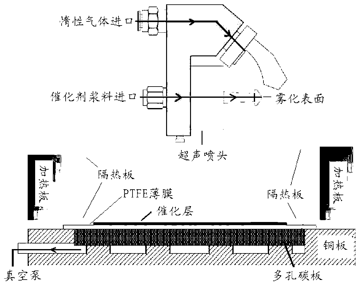
[0030]1. Spray system assembly. A copper heating plate is placed between the ultrasonic nozzle and the PTFE film, and the upper and lower parts of the heating plate are separated by a heat shield so as not to affect the normal operation of the ultrasonic nozzle. If the spraying area is rectangular, four heating plates are used to enclose it, and the heating plate is 1cm away from the edge of the spraying surface.

[0031] 2. Preparation of catalyst slurry and preparation of catalytic layer. Choose 4 mg / cm for cathode and anode respectively 2 Pt black and 4 mg / cm 2 The PtRu black catalysts are all used with a solid content loading of 0.44 mg / cm 2 The 5 wt % Nafion solution was used as the binder, both using 174.44 mg / cm 2 of isopropanol and 10.55 mg / cm 2 of water as a dispersant. The glove box was evacuated and filled with argon. The catalyst was weighed in the glove box, the slurry was prepared, and the catalyst slurry was prepared by ultrasonic dispersion using an ultr...

Embodiment 2

[0038] 1. Spray system assembly. A stainless steel heating plate is placed between the ultrasonic nozzle and the PTFE film, and the upper and lower parts of the heating plate are separated by a heat shield so as not to affect the normal operation of the ultrasonic nozzle. If the spraying area is rectangular, four heating plates are used to enclose it, and the heating plate is 2cm away from the edge of the spraying surface.

[0039] 2. Preparation of catalyst slurry and preparation of catalytic layer. Choose 2 mg / cm for cathode and anode respectively 2 Pt black and 2 mg / cm 2 PtRu black catalysts, all with a solid content loading of 0.35 mg / cm 2 The 5 wt.% Nafion solution was used as the binder, both using 92.35 mg / cm 2 isopropanol and 4.85 mg / cm 2 of water as a dispersant. The glove box was evacuated and filled with N 2 gas. The catalyst was weighed in the glove box, the slurry was prepared, and the catalyst slurry was prepared by ultrasonic dispersion using an ultrason...

Embodiment 3

[0045] 1. Spray system assembly. A stainless steel heating plate is placed between the ultrasonic nozzle and the PTFE film, and the upper and lower parts of the heating plate are separated by a heat shield so as not to affect the normal operation of the ultrasonic nozzle. If the spraying area is circular, an annular heating plate is used, and the heating plate is 0.5cm away from the edge of the spraying surface.

[0046] 2. Preparation of catalyst slurry and preparation of catalytic layer. Choose 3 mg / cm for cathode and anode respectively 2 Pt black and 3 mg / cm 2 PtRu black catalysts, all with a solid content loading of 0.33 mg / cm 2 The 5 wt.% Nafion solution was used as the binder, both using 130.83 mg / cm 2 of isopropanol and 5.84 mg / cm 2 of water as a dispersant. The glove box was evacuated and filled with N 2 gas. The catalyst was weighed in the glove box, the slurry was prepared, and the catalyst slurry was prepared by ultrasonic dispersion using an ultrasonic cell...


PUM


Abstract

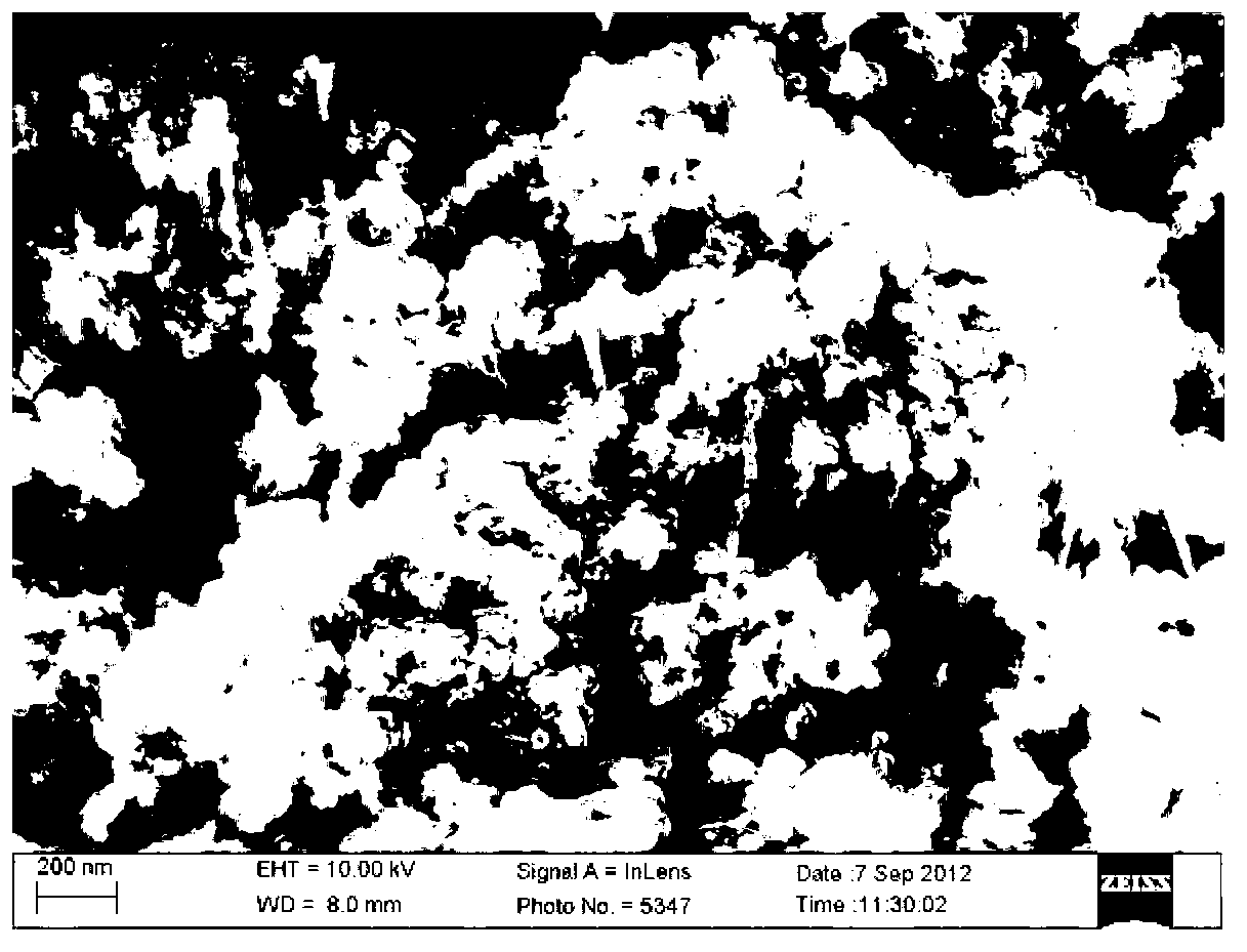
The invention discloses a method for preparing a high-efficiency membrane electrode of a direct methanol fuel cell and belongs to the structure of a high-efficiency membrane electrode component of the direct methanol fuel cell and the technical field of manufacturing of structures of high-efficiency membrane electrode components. A proton exchange membrane is adopted as an electrolyte membrane by the membrane electrode, a platinum-ruthenium black catalyst and a platinum black catalyst are respectively adopted as a cathode catalyst and an anode catalyst, isopropyl alcohol and redistilled water are adopted as dispersing agents. During preparation, an ultrasound spray-coating technology is applied in a temperature field, the agglomeration morphology of catalyst particles is adjusted by the adjustment on factors such as ingredient proportioning and preparation environments of catalyst slurry, a proton channel with a nano wire structure is prepared in a catalytic layer, so that a continuous proton channel is established effectively in the microstructure of the prepared membrane electrode, the internal resistance of the cell is reduced, the electrochemical surface area of the electrode is increased, and therefore, the efficiency of the catalytic layer of the membrane electrode is improved.

Description

technical field [0001] The invention relates to a method for preparing a high-efficiency catalytic layer structure of a direct methanol fuel cell, and belongs to the technical field of high-efficiency membrane electrode assembly structures and manufacturing of direct methanol fuel cells. Background technique [0002] Direct Methanol Fuel Cells are considered the most commercially viable portable energy source of this century to fill the electronics industry's "power gap". However, the lower battery performance is one of the main factors restricting its commercialization, especially during the battery discharge process, the anode has a higher overpotential than the cathode. Most of the existing literature is aimed at the development of new high catalytic activity catalysts and their supports, the development of new high-resistance alcohol performance proton exchange membranes or the modification of Nafion membranes, the optimization of diffusion layer and microporous layer ma...

Claims


Application Information

Patent Timeline
Patent Type & Authority Applications(China)
IPC IPC(8): H01M4/88
CPCY02E60/50
Inventor 王新东刘桂成王萌王一拓周红伟刘高阳姜颖蒋钜明吴旭苹彭冰霜
Owner UNIV OF SCI & TECH BEIJING
Learn More