Eureka AIR delivers breakthrough ideas for toughest innovation challenges, trusted by R&D personnel around the world.

Multifunctional biomass heat conversion equipment and process

A biomass, multi-functional technology, applied in inorganic chemistry, petroleum industry, carbon compounds, etc., can solve the problems of burn-through, tar black water pollution, complicated operation, etc. high effect

Inactive Publication Date: 2012-12-26
秦恒飞
View PDF7 Cites 24 Cited by
  • Summary
  • Abstract
  • Description
  • Claims
  • Application Information

AI Technical Summary

Problems solved by technology

There are three main problems: First, although the gasification equipment is diverse, the adaptability is not strong. Different gasifiers have different requirements for the type of raw material, the particle size of the raw material, and the moisture content of the raw material, and the engineering has not been truly realized. ; Second, the removal of tar in combustible gas is the biggest bottleneck of biomass gasification technology. At present, the general method of tar removal in combustible gas is a combination of physical and mechanical methods, and the combustible gas is purified by spraying, water bath, condensation, separation and other equipment , this traditional method can only remove part of the tar in the combustible gas, and there is still a considerable part of tar remaining in the combustible gas. The biggest problem with this method is that a large amount of water is wasted, and a large amount of tar black water pollution is likely to occur; the third is In the process of biomass gasification, bridging, burn-through, discontinuous discharge, and even furnace explosion are prone to occur.
[0005] At present, biomass tar catalytic cracking equipment is generally vertical and fixed, and the pores of the catalyst are easily blocked, resulting in catalyst poisoning, and once the catalyst is poisoned, the furnace needs to be shut down to replace the catalyst, the cooling cycle is long, and the operation is cumbersome.

Method used


Image

  • Multifunctional biomass heat conversion equipment and process
  • Multifunctional biomass heat conversion equipment and process
  • Multifunctional biomass heat conversion equipment and process

Examples


Embodiment 1

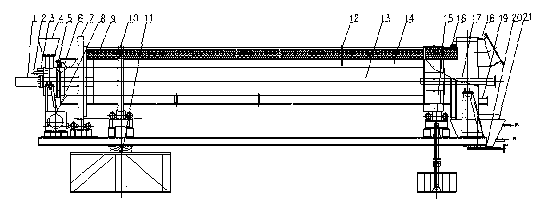
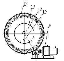
[0022] When used as a carbonization equipment, firstly adjust the screw and (8) transmission and gearbox through the (15) angle in advance according to the nature of the raw material, initially adjust the inclination angle and speed of the equipment, and then use liquefied gas to burn in the (13) combustion channel, Heat the temperature of the entire cylinder to 400°C, then use the automatic feeding mechanism to feed the raw materials into (4) the feed port, open the chimney valve, and adjust the flow of flue gas through the chimney valve until the raw material produces combustible gas during pyrolysis , withdraw the liquefied gas ignition equipment, adjust the oxygen supply of (19) the combustion port to control the carbonization temperature between 500-650 ° C, and continue to fine-tune according to the fixed carbon content and yield of the product when the equipment has product output (19) Oxygen supply to the combustion port, (15) angle adjustment screw and (8) transmission...

Embodiment 2

[0024] When used as an activation device, firstly, according to the density and size of the raw material, adjust the screw and (8) transmission and gearbox in advance through the (15) angle, initially adjust the inclination angle and speed of the equipment, and then use liquefied gas in the (13) combustion channel Combustion, heat the temperature of the entire cylinder to 600°C, then use the automatic feeding mechanism to feed the raw materials into (4) the feed port, open the chimney valve, and adjust the flue gas flow through the chimney valve, when the temperature of the cylinder reaches 800°C Withdraw the liquefied gas ignition equipment, slowly open the (2) activator inlet, and introduce a small amount of activator. After the combustible gas is generated, adjust the oxygen supply of (19) the combustion port to control the activation temperature between 850-950°C , when the equipment has product output, according to the adsorption value and decolorization value of the produ...

Embodiment 3

[0026]When used as gasification equipment, firstly adjust the screw and (8) transmission and gearbox through the (15) angle in advance according to the characteristics of the raw material, initially adjust the inclination angle and speed of the equipment, and then use liquefied gas to burn in the (13) combustion channel , heat the temperature of the entire cylinder to 500°C, then use the automatic feeding mechanism to feed the raw materials into (4) the feed port, slowly open the (2) gasification agent inlet, pass in a small amount of gasification agent, and open the chimney Valve, adjust the flue gas flow through the chimney valve, withdraw the liquefied gas ignition equipment when the temperature of the cylinder body reaches 650 °C, after the combustible gas is generated, adjust the oxygen supply of (19) the combustion port to control the activation temperature between 900-950 °C During the period, when the equipment has product output, according to the tar content of the pro...


PUM


Abstract

The invention belongs to the technical field of biomass heat conversion, and particularly relates to equipment and a process for carbonizing, activating, pyrolysis gasification, catalytic cracking of a plurality of product roads. The equipment comprises a flue pipe, an activator (gasifying agent) inlet, an auxiliary activator (gasifying agent) inlet, a feeding hole, a feeding cover seal, a forced blanking shoveling board, a gear, a drive and transmission case, heat-insulating cotton, a riding wheel, a barrel angle adjusting bolt, a temperature measuring device, a combustion channel, a product channel, an angle adjusting screw, a discharge cover seal, a lighting-up tuyere, an explosion-proof opening, a combustion-supporting opening (viewing port), a discharge sealing valve and a discharge cooler. According to the invention, the multifunctional biomass heat conversion equipment simultaneously has the functions of carbonizing, activating, pyrolysis gasification, catalytic cracking by changing an inclination angle, a rotating speed and a sealing mode; a traditional direct combustion method is changed into a bolometric method, and the problems of low yield, serious ignition loss, non-uniform reaction, small yield, large consumption and temperature control difficulty in the biomass heat conversion process are solved from the technical aspect.

Description

technical field [0001] The invention belongs to the technical field of biomass heat conversion, and in particular relates to a multi-product carbonization, activation, pyrolysis gasification, and catalytic cracking equipment and process. Background technique [0002] At present, the carbonization equipment used in industry mainly includes earthen kiln, retort, vertical tank furnace, etc. These equipments have the advantages of simple structure and easy operation, but they have some disadvantages during production, such as earthen kiln occupies a large area , The temperature is not easy to control, it is entirely based on experience, the color of the smoke and the smell of the smoke are operated, and the smoke cannot be processed. The output of the retort is small, and it is operated intermittently, so it cannot be continuously produced, and the quality of each furnace is not uniform. The vertical tank furnace also has the disadvantages of large floor area, inability to migr...

Claims


Application Information

Patent Timeline
IPC IPC(8): C10B53/02C10B57/00C10B57/18C10B57/12C10B47/00C01B31/10C10J3/60C10J3/66C01B32/336
Inventor 秦恒飞项东升周月胡志杰高成
Owner 秦恒飞
Why Eureka
Eureka Blog
Learn More