Safety control system and safety controller in failure mode of vehicle electric drive system
A safety controller, electric drive system technology, applied in the control system, AC motor control, electrical components and other directions, can solve the problems of high voltage at the positive and negative terminals of the battery, damage to the capacitor CDC and battery, etc., to reduce short-circuit current and solve driving problems. Impact problems, the effect of improving safety and drivability
- Summary
- Abstract
- Description
- Claims
- Application Information
AI Technical Summary
Problems solved by technology
Method used
Image
Examples
Embodiment 1
[0063] The safety control system in the failure mode of the vehicle electric drive system. The electric drive system includes a battery, a three-phase bridge inverter, and a three-phase drive motor. The three-phase bridge inverter converts the DC output from the battery into a three-phase AC. Drive the three-phase drive motor; the safety control system includes a motor speed sensor, a motor speed sensor state diagnostic device, a battery voltage sampling circuit, and a safety controller;
[0064] The motor speed sensor is used to detect the speed of the drive motor of the electric drive system;
[0065] The motor speed sensor state diagnostic device is used to detect the state of the motor speed sensor;
[0066] The battery voltage sampling circuit is used to detect the voltage between the positive and negative terminals of the battery of the vehicle electric drive system;
[0067] The safety controller is used to respectively output safety control signals to the power switch...
Embodiment 2
[0083]Based on Embodiment 1, the safety control system under the failure mode of the vehicle electric drive system also includes a gear position sensor, a wheel speed sensor, and an engine speed sensor;
[0084] Gear position sensor, used to collect the gear position of the transmission and output it to the safety controller;
[0085] The wheel speed sensor is used to collect the rotation speed of the wheel and output it to the safety controller;
[0086] The engine speed sensor is used to collect the engine speed and output it to the safety controller;
[0087] In step 2, if the state of the motor speed sensor is faulty, the safety controller determines the current driving motor speed according to the position of the motor in the vehicle topology, and then proceeds to step 3. The method for determining the current driving motor speed is:
[0088] If the drive motor is connected to the reducer or transmission, the safety controller determines the current drive motor speed acc...
Embodiment 3
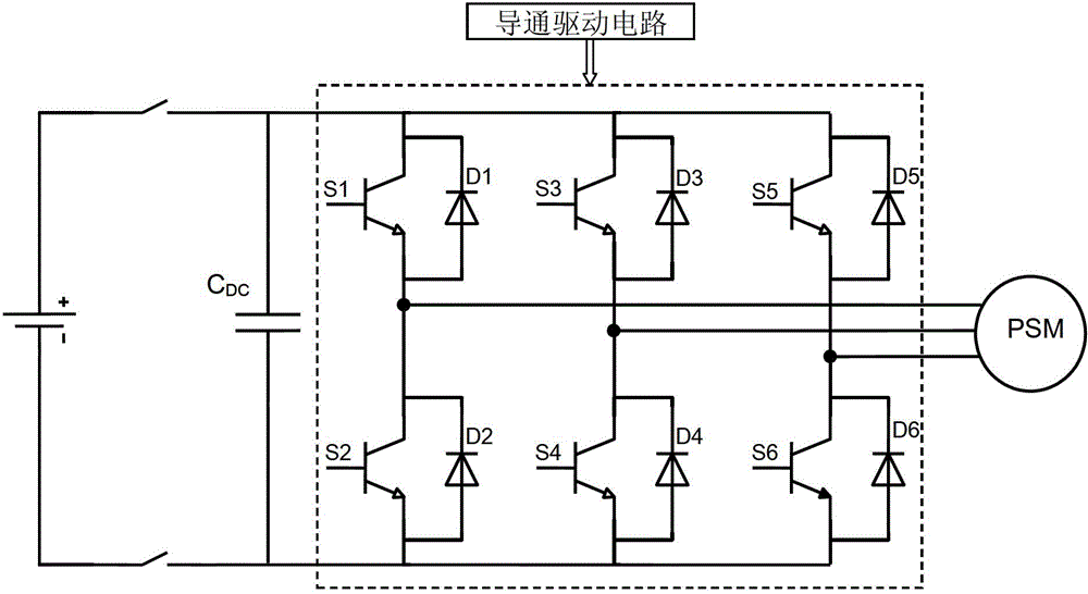
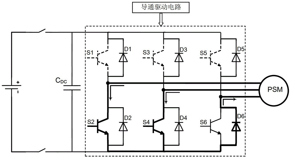
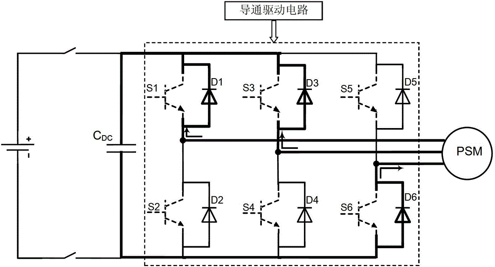
[0091] Based on Embodiment 1, the three-phase bridge inverter such as figure 1 As shown, it includes the first power switch tube S1, the second power switch tube S2, the third power switch tube S3, the fourth power switch tube S4, the fifth power switch tube S5, the sixth power switch tube S6, the first reverse Freewheeling diode D1, second reverse freewheeling diode D2, third reverse freewheeling diode D3, fourth reverse freewheeling diode D4, fifth reverse freewheeling diode D5, sixth reverse freewheeling diode D6, Capacitor CDC, conduction drive circuit; power switch tube can use power transistor (GTR), gate turn-off thyristor (GTO), power field effect transistor (PowerMOSFET), insulated gate bipolar transistor (IGBT), integrated gate switch Thyristor (IGCT), symmetrical gate commutated thyristor (SGCT), etc.;
[0092] The first power switch tube S1, the third power switch tube S3, the fifth power switch tube S5, the first reverse freewheeling diode D1, the third reverse f...
PUM
 Abstract
Description
Claims
Application Information
 - Generate Ideas
- Intellectual Property
- Life Sciences
- Materials
- Tech Scout
- Unparalleled Data Quality
- Higher Quality Content
- 60% Fewer Hallucinations
Browse by: Latest US Patents, China's latest patents, Technical Efficacy Thesaurus, Application Domain, Technology Topic, Popular Technical Reports.
© 2025 PatSnap. All rights reserved.Legal|Privacy policy|Modern Slavery Act Transparency Statement|Sitemap|About US| Contact US: help@patsnap.com


