
Method for improving power density of electric energy conversion device

A technology of electric energy conversion and power density, applied in circuits, electrical components, electrical digital data processing, etc., can solve problems such as inability to use voltage as much as possible, failure to reach thermal balance, temperature rise, etc., to reduce test workload , improve the power density, the effect of clear principle

Active Publication Date: 2012-08-01
NAVAL UNIV OF ENG PLA
View PDF3 Cites 9 Cited by
  • Summary
  • Abstract
  • Description
  • Claims
  • Application Information

AI Technical Summary

Problems solved by technology

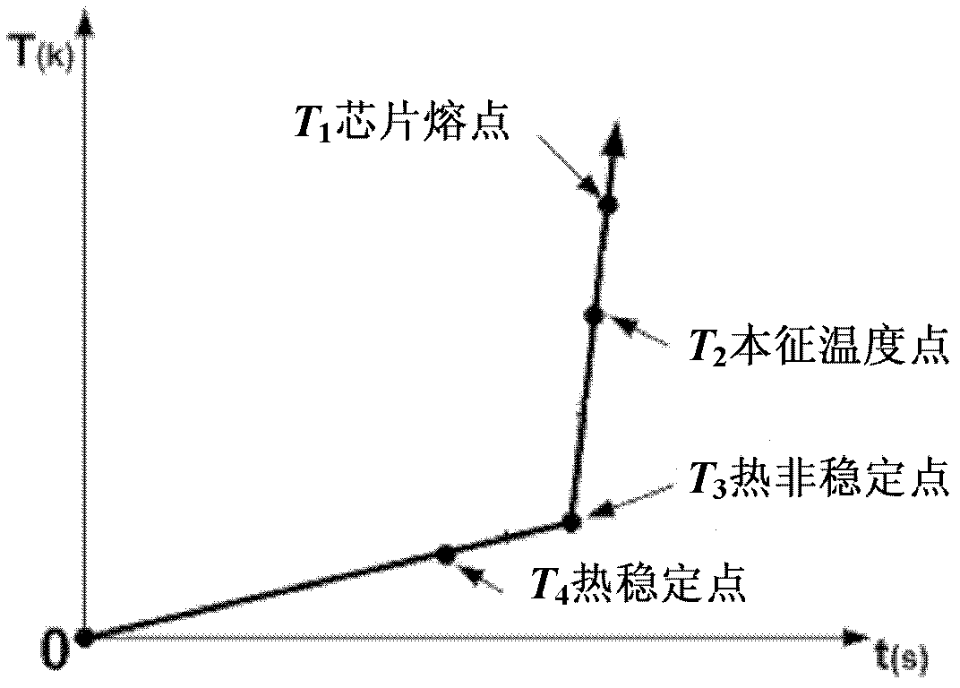
[0003] The essence of IGBT thermal breakdown failure is that the heat generated by the IGBT internal chip and the heat taken away by the external heat sink cannot reach a thermal balance, the heat cannot be completely dissipated, and heat accumulation is formed inside, and the positive feedback effect between IGBT power consumption and temperature As a result, the junction temperature continues to rise. After reaching a certain level, the temperature rises to the intrinsic temperature due to the sharp increase of the leakage current to form a short circuit, and finally fails.
Conventional design methods generally design various parameters according to the maximum junction temperature given in the manual, which cannot reflect the nature of IGBT thermal failure, nor can it achieve the maximum use of parameters such as voltage, current, switching frequency, and junction temperature. It is an experience-based extensive design method

Method used

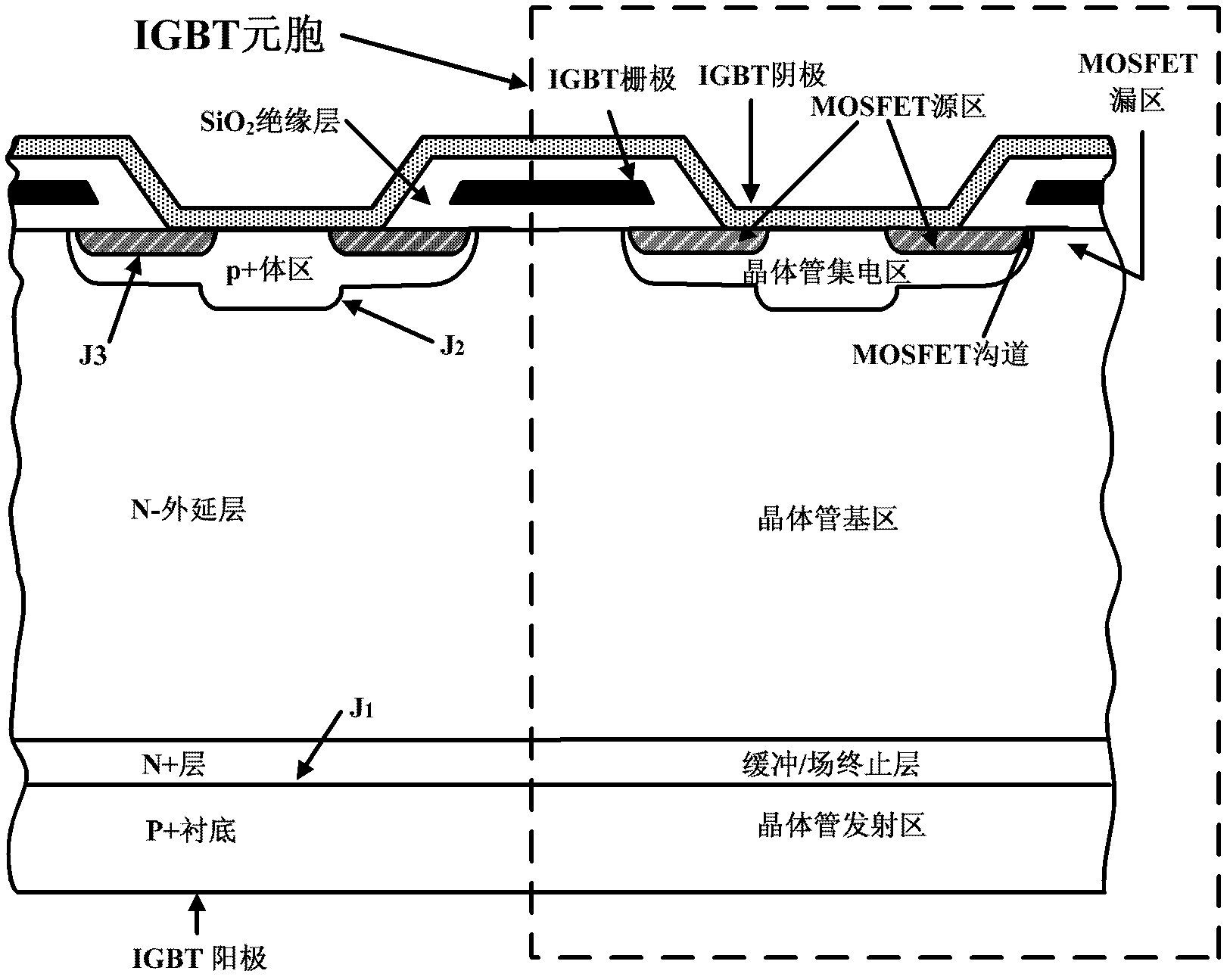
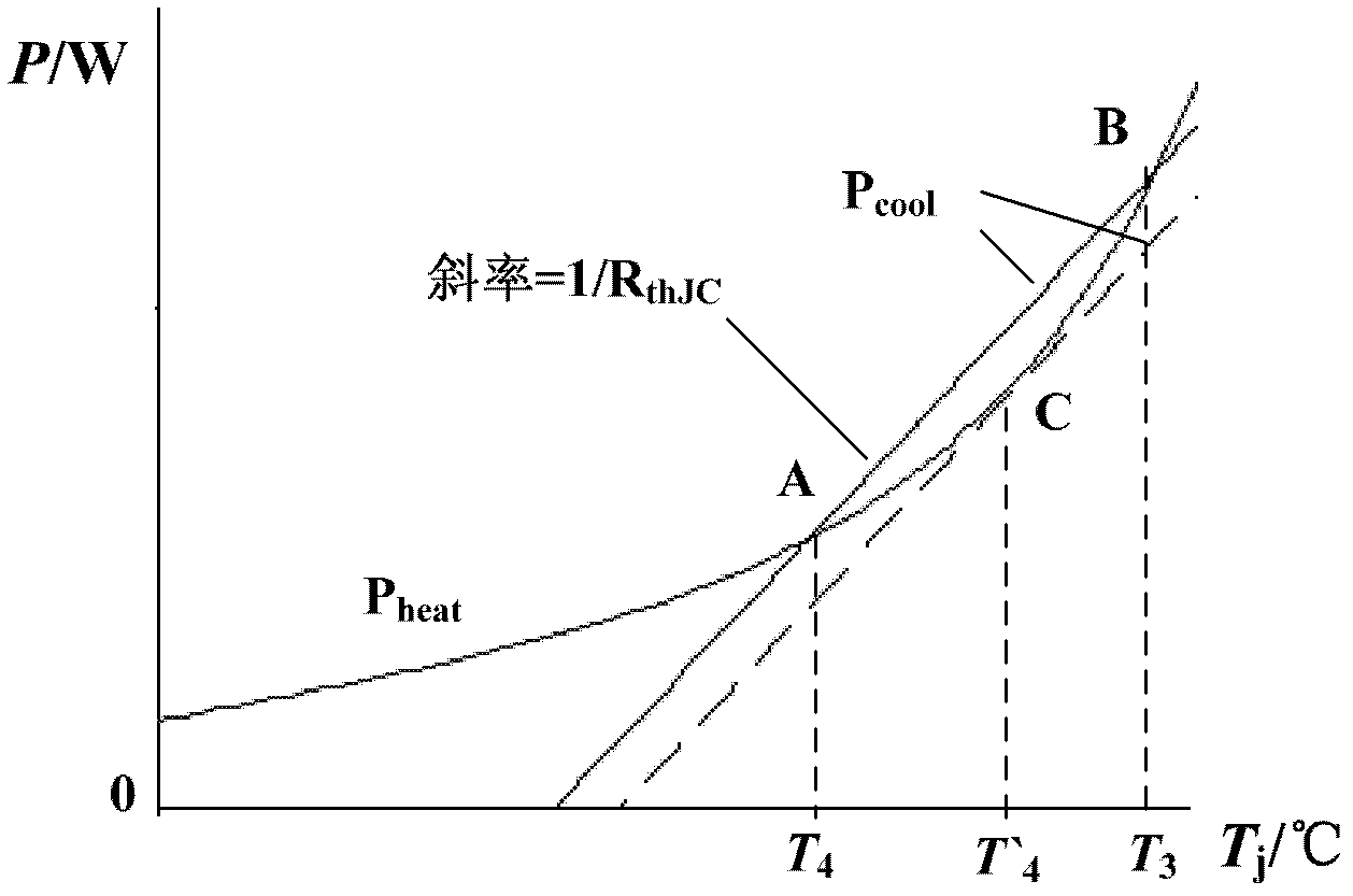

Image

  • Method for improving power density of electric energy conversion device
  • Method for improving power density of electric energy conversion device
  • Method for improving power density of electric energy conversion device

Examples


example

[0121] The analysis will be explained below in combination with specific examples. The IGBT device model is selected as GD50HFL120C1S. This device adopts the chip of ABB Company and is packaged in China. Its rated voltage and DC current are 1200V and 50A respectively. It is a soft pass-through two-unit half-bridge module. A chopper circuit with diode freewheeling is used, and the circuit conditions are set as follows: voltage 600V, duty cycle 0.5, case temperature 80°C, and it is required to design the limit of switching frequency under different current conditions. The design steps are:

[0122] (1) Since this type of device belongs to the PT type, the PT type model is adopted. From the conduction steady state, switching transient and off-state mathematical models, the expressions of conduction voltage drop, switching voltage, switching current and collector leakage current are obtained, and the conduction power consumption, switching power consumption and The off-state pow...


PUM


Abstract

The invention relates to a method for improving the power density of an electric energy conversion device and discloses an IGBT (insulated gate bipolar transistor) parameter limit use design method based on thermal equilibrium analysis; according to an IGBT thermal breakdown failure mechanism, an established IGBT electric heating model is adopted for simulation to obtain a temperature curve on the breakover power consumption, the switching power consumption and the off-state power consumption in the condition with given parameters, temperature curves of the IGBT total power consumption is obtained by addition, a heat transfer power consumption curve is obtained according to junction-shell steady state thermal resistance, and the thermal equilibrium analysis is carried out by combining the IGBT total power consumption curve with the heat transfer power consumption curve, wherein the junction temperature during tangency of the two curves is the IGBT limit junction temperature, and the corresponding parameter value is the limit use value under the circuit condition. According to the invention, the IGBT parameter limit use design method is clear in principle and strong in operability, the actual test work load is reduced, the accurate quantization of parameter limit use is achieved, and the power density of the device is improved.

Description

technical field [0001] The invention belongs to the field of large-capacity power electronic devices, and in particular relates to a method for increasing the power density of an electric energy conversion device. The method is realized by using IGBT parameters as much as possible based on heat balance analysis. Background technique [0002] The IGBT manual usually gives boundary parameters such as collector-emitter maximum voltage, collector maximum current, and maximum operating junction temperature. In the current use design, these boundary parameter values ​​​​are generally used as the maximum operating boundary, and also reserved Larger margin, a certain derating use, this selection and design standards are far from reaching the purpose of accurate quantification and optimal design of devices. Special high-performance power electronic systems have the characteristics of large capacity, high power density and high reliability. If this design method is still adopted, it w...

Claims


Application Information

Patent Timeline
Patent Type & Authority Applications(China)
IPC IPC(8): H01L21/331G06F19/00
Inventor 唐勇汪波孙驰胡安陈明肖飞刘宾礼罗毅飞
Owner NAVAL UNIV OF ENG PLA
Learn More