
A kind of rare earth permanent magnet and its preparation method

A rare earth permanent magnet and magnet technology, which is applied in the manufacture of magnetic objects, permanent magnets, inductors/transformers/magnets, etc., can solve the problems of magnet corrosion resistance, poor solubility of powder in water or organic solvents, uneven distribution, etc. Achieve the effect of improving coercivity, improving uniformity and reducing residues

Active Publication Date: 2016-12-14
BEIJING ZHONG KE SAN HUAN HI TECH +1
View PDF7 Cites 0 Cited by
  • Summary
  • Abstract
  • Description
  • Claims
  • Application Information

AI Technical Summary

Problems solved by technology

[0004] However, in this method, rare earth fluorides, oxides, and oxyfluorides will have uneven residues after thermal diffusion on the surface of the magnet. Although the surface is removed by acid / alkali treatment or sandblasting or processing in the later stage, due to the diffusion The depth is limited (according to the diffusion depth disclosed in Chinese Patent Application Publication No. CN1838342, the diffusion depth is about 20 μm or more), if too much skin is removed, the coercive force will increase little or not; if less skin is removed, the surface or near surface will be uneven The residue of fluorine, especially the residue of fluorine, has a great influence on the corrosion resistance of the magnet. Generally, the surface of the magnet is protected by plating or coating, but the magnet plating or coating obtained by diffusing rare earth Dy and Tb to the surface After that, there will often be a problem of poor bonding strength between the substrate and the coating or coating, which will affect the corrosion resistance of the magnet after coating or coating
And CN1898757 patent application does not have relevant expression to the corrosion resistance of magnet
[0005] The bonding strength between the substrate and the coating or coating is poor after the magnet is plated or coated by the method described in CN1898757. The reason is that when the powder is placed on the surface of the magnet, the powder is in water or organic solvent. The solubility is very poor, and it cannot be evenly distributed on the surface of the magnet. After thermal diffusion, there is a melt of unevenly distributed powder on the surface of the magnet.

Method used


Image

  • A kind of rare earth permanent magnet and its preparation method
  • A kind of rare earth permanent magnet and its preparation method
  • A kind of rare earth permanent magnet and its preparation method

Examples


Embodiment 1-2

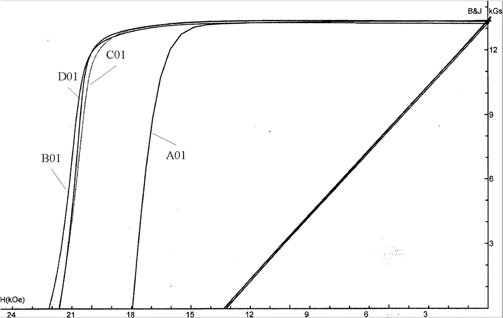
[0037] Smelt the alloy to get (Nd, Pr) a Dy b Fe (1-a-b-c) B c (a = 14.5, b = 0.6, c = 5.8, a, b, and c are atomic percentages), the ingot alloy is coarsely crushed and hydrogen crushed according to the conventional method, jet milled into fine powder, and then mixed Uniform, then oriented by a 2.0T magnetic field and pressed into shape, subjected to 180MPa isostatic pressing, and the green body was sintered at 1070°C for 3 hours to obtain a rough magnet, and the sintered rough magnet was cut into small square pieces of 12mm×12mm×2mm for processing magnet. Divided into A (original sample), B (comparative example), C (example 1), D (example 2) four groups of 100 pieces each. The two groups of samples A and B are comparative samples, in which the samples of group A are not treated, and the samples of group B are pickled with a mass ratio of 3% nitric acid aqueous solution, and then DyF is arranged on the surface of the samples. 3 , Dy 2 o 3 and DyOF powder (the mass perce...

Embodiment 3

[0048] Smelting the alloy by strip technology to obtain (Nd, Pr, Sc) a Dy b co d Fe (1-a-b-c-d) B c (a=15, b=0.6, c=5.8, d=1.0, a, b, c, and d are atomic percentages), the flakes are subjected to hydrogen crushing and air-jet milling in a conventional manner to make fine powder , and then mixed evenly, and then oriented by a 2.0T magnetic field and pressed into shape, subjected to 180MPa isostatic pressing, and the green body was sintered at 1060°C for 3 hours to obtain a rough magnet, and the sintered rough magnet was cut into small square pieces of 12mm×12mm×2mm As a belt handle magnet. The magnet to be treated carries out routine pickling through the nitric acid aqueous solution of 4% mass ratio, then arranges the fluoride powder of R2 on its surface, the nitrate powder of R3 and the phosphate powder of R4, R2 is Dy and Y (Dy, Y mass ratio 3: 1), R3 is Tb, R4 is Tb, three powder mass percentages are respectively 73%, 12%, 15%, and the average particle size is respectiv...

Embodiment 4

[0050] The alloy is smelted by strip strip technology to obtain Nd a Dy b Fe (1-a-b-c-d) Al d B c (a=15, b=0.3, c=6.0, d=0.3, a, b, c, d are atomic percentages) of flakes, the flakes are subjected to hydrogen crushing and jet milling in a conventional manner to make fine powder , and then mixed evenly, and then oriented by a 2.0T magnetic field and pressed into shape. After 180MPa isostatic pressing, the green body was sintered at 1060°C for 3.5h, and then aged at 450°C for 3.5h to obtain a rough magnet. The aged blank was cut into A small square piece of 12mm×12mm×3mm is used as the magnet to be processed. The magnet to be treated carries out conventional alkali washing through 2% mass ratio of sodium silicate aqueous solution, then arranges the fluoride powder of R2 on its surface, the nitrate powder of R3 and the phosphate powder of R4, R2 is Tb and Sc (Tb and Sc The mass ratio is 4:1), R3 is Dy and Ho (the mass ratio of Dy and Ho is 4:1), R4 is Dy and Er (the mass rat...


PUM

PropertyMeasurementUnit
particle sizeaaaaaaaaaa
Mohs hardnessaaaaaaaaaa

Abstract

A rare earth permanent magnet that can increase the coercive force of the magnet without reducing the remanence and energy product of the magnet, and at the same time can not reduce the bonding strength between the substrate and the coating or coating after plating or coating, and prepare the magnet The method is as follows: first, dissolve the powder containing R2 fluoride, R3 nitrate and R4 phosphate in water or alcohol to prepare a solution; arrange the above solution evenly on the surface of the magnet to be treated; then dehydrate the magnet to be treated or alcohol treatment; finally, the treated magnet is subjected to diffusion heat treatment to obtain the treated magnet. The method used in the present invention can improve the uniformity of the powder on the surface of the magnet, reduce the powder residue on the surface of the magnet after thermal diffusion, improve the coercive force of the magnet, and not reduce the bonding between the substrate and the coating or coating after plating or coating strength.

Description

technical field [0001] The invention relates to a rare earth permanent magnet and a method for preparing the magnet. In particular, it relates to a rare earth permanent magnet that improves the bonding strength of the plating layer or coating and the substrate on the basis of increasing the coercive force of the magnet and the method for preparing the magnet. Background technique [0002] Rare earth permanent magnets have excellent magnetic properties. In recent years, they have been widely used in the fields of air-conditioning motors, hybrid vehicles and wind power generation. The use of magnets in these fields has to face high temperature and humid environments. in salty humidity. Therefore, not only magnets are required to have high magnetic properties, but also high corrosion resistance is required. [0003] The industry has done a lot of work to improve the magnetic properties of magnets. In recent years, in-depth research has been done on how to improve the coercive...

Claims


Application Information

Patent Timeline
Patent Type & Authority Patents(China)
IPC IPC(8): H01F7/02H01F1/053H01F41/02C23C22/68C23C22/03C23C22/82C22F1/02
Inventor 钮萼李正陈超王进东韦立立王惠新饶晓雷胡伯平
Owner BEIJING ZHONG KE SAN HUAN HI TECH
Learn More