
Method for manufacturing ceiling

A production method and ceiling technology, applied in the direction of chemical instruments and methods, natural mineral layered products, layered products, etc., can solve the problems of low hardness, insufficient adhesion, and short service life, etc., to achieve extended use Long life, moisture-proof and sound insulation effect, and the effect of improving the service life

Inactive Publication Date: 2012-07-04
舟山市金海舟船舶设备有限公司
View PDF7 Cites 4 Cited by
  • Summary
  • Abstract
  • Description
  • Claims
  • Application Information

AI Technical Summary

Problems solved by technology

However, the aluminum-plastic panels selected for this ceiling are not rigid enough, and the hardness is not high, so the ceiling produced is not high in hardness and wear-resistant, and the corrosion resistance of the plastic liner in the ceiling is not strong enough, and the sound absorption effect is not enough Well, so the ceiling is not corrosion-resistant, and the sound insulation effect is not good. In addition, the ceiling is made by directly bonding the aluminum-plastic panel, the plastic liner and the aluminum-plastic bottom plate, and then pressed by a molding machine, and the bonding degree between the panels is not strong enough , so the ceiling is easy to split and the service life is not long, so the manufacturing method of the ceiling needs to be further improved

Method used


Image

  • Method for manufacturing ceiling
  • Method for manufacturing ceiling
  • Method for manufacturing ceiling

Examples


Embodiment 1

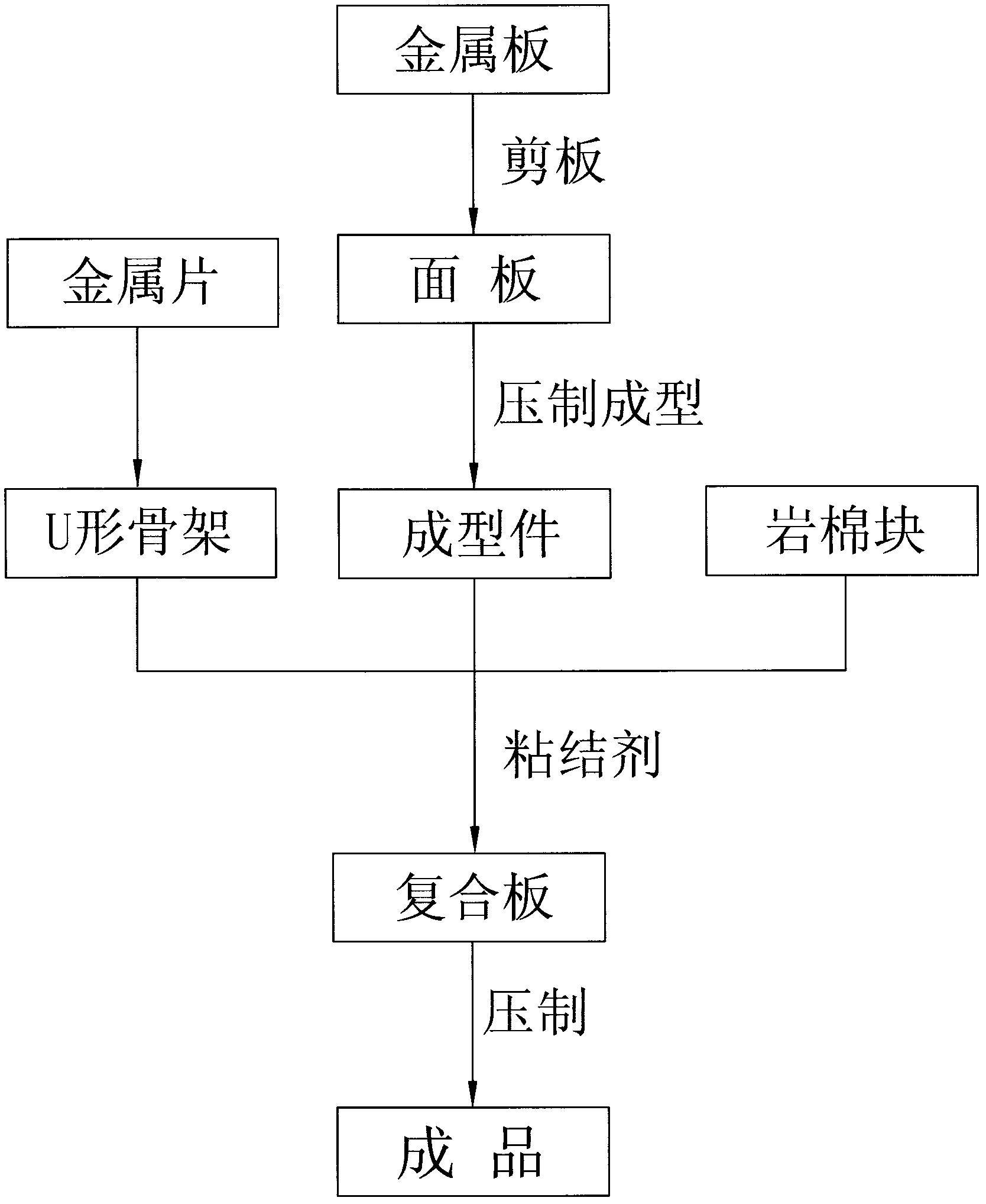
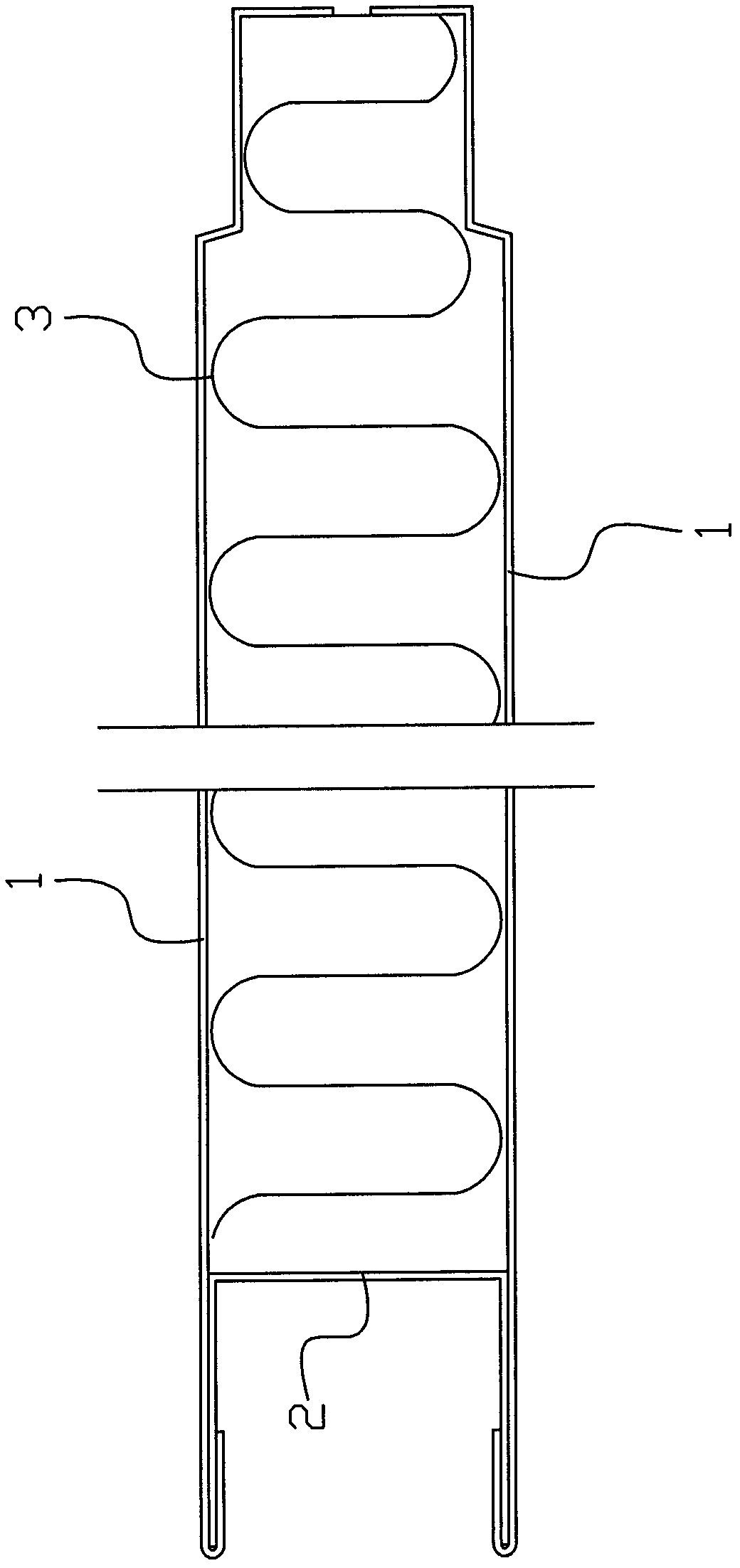
[0030] Embodiment one: if Figure 1 to Figure 3 Shown, the manufacture method of this ceiling comprises the following steps:

[0031] 1. Cut the metal plate 1 into required specifications and sizes; the metal plate 1 in this embodiment is preferably a plastic-coated steel plate or a galvanized plate

[0032] 2. Place the cut plastic-coated steel sheet or galvanized sheet in a rolling mill to press and form it to become a formed part;

[0033] 3. Fold the iron sheet into a U-shape to form a U-shaped skeleton 2 for use;

[0034] 4. Cut the rock wool block 3 into the desired shape and thickness, and set aside;

[0035] 5. Insert the spare U-shaped skeleton 2 into the notch curling of the molded part, then evenly apply the adhesive on the molded part, and then spread the cut rock wool block 3 on the molded part coated with adhesive , and then another molded piece coated with adhesive is covered on the laid rock wool block 3 to form a composite board; the binder is a polymer con...

Embodiment 2

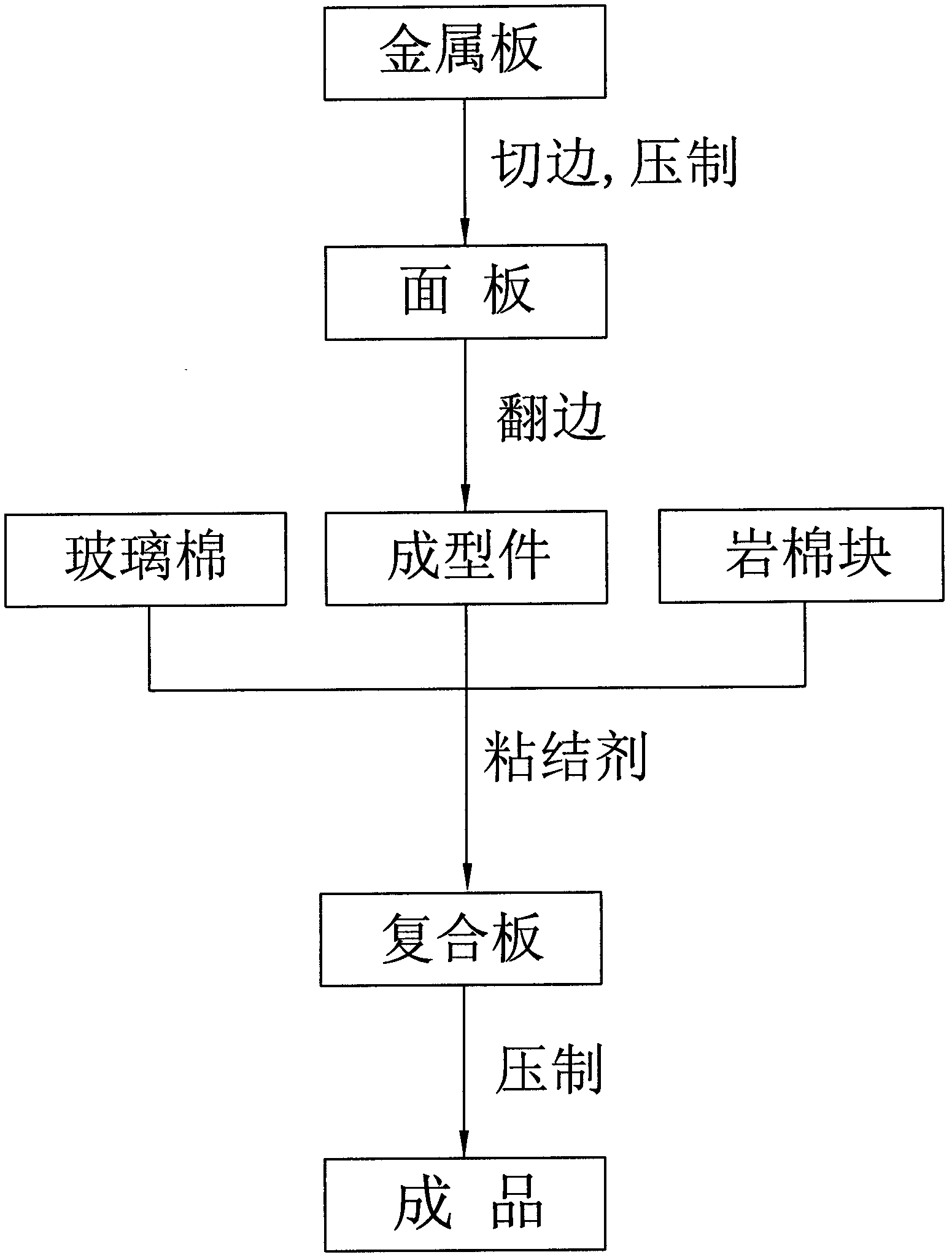
[0037] Embodiment two: if Figure 1 to Figure 3 Shown, the manufacture method of this ceiling comprises the following steps:

[0038] 1. Cut the plastic-coated steel sheet or galvanized sheet into the required size;

[0039] 2. Place the cut plastic-coated steel sheet or galvanized sheet in a rolling mill to press and form it to become a formed part;

[0040] 3. Place the formed part in the flanging mold for flanging, flanging to the required height, and set aside;

[0041] 4. Cut the rock wool block 3 into the desired shape and thickness for later use; the density of the rock wool block 3 is 120-150kg / m;

[0042] 5. Apply adhesive evenly on the molded part, and spread the prepared rock wool block 3 on the molded part coated with adhesive to form a composite board; the composite board is also filled with insulating materials.

[0043] 6. Next, place the composite board in a pressing mold and press it, so that the rock wool block 3 is firmly combined with the molded part thr...


PUM

PropertyMeasurementUnit
Densityaaaaaaaaaa

Abstract

The invention discloses a method for manufacturing a ceiling. The method is characterized by comprising the following steps of: 1, cutting a plate; 2, molding a panel material; 3, folding a notch framework; 4, cutting a rock wool block; 5, embedding a spare U-shaped framework into a notch curled edge of a molded piece, coating an adhesive on the molded piece uniformly, laying the cut rock wool block on the molded piece coated with the adhesive, and covering another molded piece coated with the adhesive on the upper side of the laid rock wool block to form a composite plate; and 6, pressing to obtain a finished product. Compared with the prior art, the method has the advantages that: the ceiling has moisture resistance, mildew resistance, good sound insulation effect, high abrasion resistance and long service life and is difficult to age; and in addition, a notch of the ceiling is fixed by the framework folded by an iron sheet, so that the ceiling can be effectively prevented from falling apart, and the service life of the ceiling can be further prolonged.

Description

technical field [0001] The invention relates to the technical field of making decorative boards, in particular to a method for making a ceiling. Background technique [0002] There is a Chinese invention patent whose application number is CN200810198274.0 titled "A Preparation Method for Composite Ceiling", which discloses a preparation method for composite ceiling. The method includes the following steps: A. The middle part has an aluminum-plastic panel with a concave cavity, an aluminum-plastic bottom plate corresponding to the size of the aluminum-plastic panel, and a plastic liner with a thickness corresponding to the depth of the aluminum-plastic panel cavity; B. Put the plastic liner into the cavity of the aluminum-plastic panel, Bond and fix the aluminum-plastic panel, plastic liner and aluminum-plastic bottom plate by glue; C. Press the glued and fixed aluminum-plastic panel, plastic liner and aluminum-plastic bottom plate through a molding machine, and then trim the...

Claims


Application Information

Patent Timeline
IPC IPC(8): E04F13/075B32B15/04B32B19/08B32B7/12
Inventor 金良成马志新翁鸣放毛文辉
Owner 舟山市金海舟船舶设备有限公司
Learn More