
Method for self-lubricating treatment of laser micro-texture of bearing

A processing method and micro-modeling technology, which is applied to bearing components, shafts and bearings, laser welding equipment, etc., can solve problems that affect bearing fitting accuracy and support stiffness, increase process difficulty and cost, and affect lubrication effects, etc., to achieve savings Dosage, ensure stable supply and uniform coating, and ensure the effect of bearing capacity

Inactive Publication Date: 2011-10-26
JIANGSU UNIV
View PDF16 Cites 54 Cited by
  • Summary
  • Abstract
  • Description
  • Claims
  • Application Information

AI Technical Summary

Problems solved by technology

The whole layer coating and sintering method is adopted, and the thickness of the lubricating coating reaches 0.5-2.5 mm, which affects the matching accuracy and support rigidity of the bearing.
The patent published in 2009 (application number: 200810235590.0) discloses a three-layer self-lubricating sliding bearing structure. Due to the addition of a layer of porous copper powder sintering layer, the difficulty and cost of the process are greatly improved, and the improvement of machining accuracy is also limited.
This patent uses laser micromachining small holes to form silver diffusion channels, but there is no pre-embedded lubricant in the channels, which will affect the lubrication effect
The patent published in 2009 (application number: 200910033454.8) proposed a laser surface bionic structure and impact strengthening method, but did not involve surface self-lubricating treatment
Metal-based inlaid self-lubricating bearings (mainly copper-based materials) are easy to soften at high temperatures due to their low load-carrying capacity, and are difficult to adapt to high-temperature and heavy-load environments such as metallurgy and engineering machinery.

Method used


Image

  • Method for self-lubricating treatment of laser micro-texture of bearing
  • Method for self-lubricating treatment of laser micro-texture of bearing
  • Method for self-lubricating treatment of laser micro-texture of bearing

Examples


Embodiment Construction

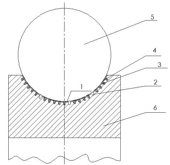
[0042] to combine figure 1 , When the bearing is in motion, due to heat and friction, the solid lubricant 3 will continuously seep out and transfer to play the role of lubrication and friction reduction. The machining of the micro-cavity 11 or the micro-groove is realized by removing the material by the laser. Through the strengthening effect of the laser on the metal material, the strengthening of the bearing bearing area is realized. By reserving micro-cavities 11 or micro-grooves, the collection of lubricating oil (grease) and abrasive particles during operation is realized, and the adaptability to complex working conditions is improved. At the same time, laser micro-modeling and self-lubricating treatment can also be carried out on the raceway of the outer ring of the bearing according to the needs.

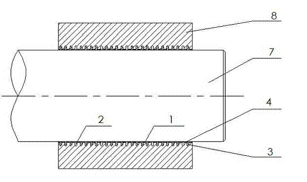
[0043] to combine figure 2 , Since the shaft 7 and the sliding bearing sleeve 8 are always in a state of sliding friction, using solid lubrication treatment, the effect o...


PUM


Abstract

The invention discloses a method for self-lubricating treatment of laser micro-texture of bearings. The invention comprises the following steps: firstly performing laser micro-processing technology of micro recessed cavities or micro grooves on a bearing surface, and then performing molding and bonding technology by a self-lubricating composite material on the bearing surface; the self-lubricating composite material comprises the following components by mass: 10-15% of polyimide (PI); 8-13% of graphite powder; 40-50% of polytetrafluoroethylene; 25-29% of MoS2; 0-5% of additives. By the self-lubricating treatment of laser micro-texture of a bearing, the invention guarantees the bearing capacity and the fitting accuracy of the bearing, realizes an optimized distribution of the lubricant on the bearing working surface, and improves comprehensive performance of antifriction and wear resistance of the bearing under complicated working conditions.

Description

technical field [0001] The invention relates to self-lubricating bearing technology, in particular to a self-lubricating compound treatment technology for bearing laser micro-modeling, which is used to solve the problem of bearing lubrication under special and complicated working conditions. Background technique [0002] At present, most metallurgical enterprises use traditional mechanical bearings lubricated by lubricating oil and grease. Due to long-term exposure to harsh environments such as high temperature, heavy load, impact, and dust, lubricating oil and grease are prone to failure. It requires a large amount of cooling water and lubricating grease during use, which not only causes great energy waste and pollutes the environment, Moreover, the use stability of the bearing is poor, and it is often damaged, so it is difficult to meet the normal requirements of production. At the same time, the grease-lubricated joint sliding bearings widely used in construction machine...

Claims


Application Information

Patent Timeline
IPC IPC(8): F16C33/00F16C33/10F16C33/66F16C33/58B23K26/36C23C24/08
CPCF16C33/6696F16C33/1095F16C33/585
Inventor 华希俊张培耘鲍培德杜志华
Owner JIANGSU UNIV
Learn More