
Laser shock method

A technology of laser shock and metal materials, which is applied in the direction of ion implantation plating, coating, metal material coating technology, etc., can solve problems such as easy foaming and peeling or sharp corner peeling, material distortion, and large surface brittleness, etc., to achieve improvement Anti-corrosion and anti-fatigue properties, increase strength and hardness, and reduce porosity

Active Publication Date: 2011-10-12
ZHANGJIAGANG FURUI SPECIAL EQUIP CO LTD
View PDF3 Cites 26 Cited by
  • Summary
  • Abstract
  • Description
  • Claims
  • Application Information

AI Technical Summary

Problems solved by technology

In this way, the ferrite and martensite components on the surface are transformed into austenite, and the strength of the formed surface layer is improved by nitrogen through solid solution strengthening. However, the disadvantage of this technology is that it is difficult to control the furnace temperature and infiltrate the material. Nitriding layer will appear reticular, corrugated, needle-like or fishbone-like nitrides, the depth of the nitriding layer is shallow, the hardness is uneven, there are soft spots, the surface hardness is low, the surface layer is brittle and easy to bubble and peel off or peel off at sharp corners. After nitriding, the material will be distorted, and the nitriding layer is not dense and has poor corrosion resistance

Method used


Image

  • Laser shock method
  • Laser shock method
  • Laser shock method

Examples


Embodiment Construction

[0012] The present invention will be further described below in conjunction with the accompanying drawings and embodiments, but the present invention should not be limited to the embodiments.

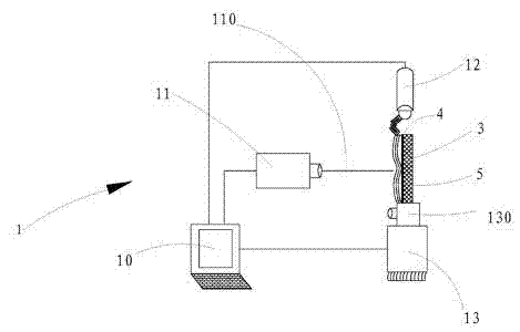
[0013] see Figure 1 to Figure 4 , a laser shock method, the steps are:

[0014] A) Provide a laser shock device 1 and a vacuum ion coating machine 2, the laser shock device 1 includes a computer control system 10, a high-power laser 11, an automatic water spray device 12 and a workbench 13, the workbench 13 is provided with a clamping The first fixture 130 for holding the workpiece. In this embodiment, the workbench 13 is a five-axis linkage workbench. The vacuum ion coating machine 2 is provided with a second fixture 20 for clamping workpieces, and the high-power laser 11 , automatic water spray device 12 and workbench 13 are controlled by a computer control system 10 .

[0015] B) Cover the surface of the cleaned metal material 3 with an aluminum foil absorption layer 4 to enhance ...


PUM


Abstract

The invention discloses a laser shock method. The method comprises the following steps: (A) providing a laser shock device and a vacuum ion plating machine, wherein the laser shock device comprises a computer control system, a high-power laser, an automatic water sprayer and a worktable, the worktable is equipped with a first fixture and the vacuum ion plating machine is equipped with a second fixture; (B) covering an aluminum foil absorbing layer on the surface of a metal material; (C) controlling the automatic water sprayer to spray water to the surface of the aluminum foil absorbing layer by means of the computer control system; (D) controlling the worktable to move by means of the computer control system; (E) controlling the high-power laser to emit laser beams to the aluminum foil absorbing layer by means of the computer control system; and (F) finally removing the aluminum foil absorbing layer, placing the metal material in the vacuum ion plating machine and forming a graphite coating on the surface of the metal material by utilizing a physical vapor deposition method. By utilizing the laser shock method, surface strength and hardness of the metal material can be improved and cavitation erosion can be effectively avoided.

Description

technical field [0001] The invention relates to the field of laser shock strengthening, in particular to a laser shock method. Background technique [0002] The surface strength of the aluminum alloy volute of the aero-engine fuel supply system decreases due to cavitation. There are fatigue cracks and erosion morphology on the surface of the cavitation zone, and the material is damaged and destroyed under the combined action of cavitation and erosion. When the hydropower station operates under load conditions, cavitation problems will also occur. Holes, gaps, and shedding will appear on the blades of the turbine, which will damage the flow-through parts of the turbine. The unit will generate a lot of noise and vibration at the same time. The output and efficiency of the turbine reduce. Vibration cavitation with a large area of ​​irregular corrosion will appear on the surface of the bearing under working conditions. Therefore, cavitation is also an important form of damage ...

Claims


Application Information

Patent Timeline
IPC IPC(8): C21D1/09C22F3/00C23C14/06C23F17/00
Inventor 殷劲松张磊鲁金忠戴峰泽张永康张建红
Owner ZHANGJIAGANG FURUI SPECIAL EQUIP CO LTD
Learn More