
Maskless photoetching alignment system

A maskless lithography and alignment system technology, applied in microlithography exposure equipment, optics, photolithography process exposure devices, etc., can solve the problems of complex structure and difficult implementation of the alignment system, and improve the alignment accuracy. , low cost, simple operation effect

Inactive Publication Date: 2011-09-21
INST OF OPTICS & ELECTRONICS - CHINESE ACAD OF SCI
View PDF8 Cites 19 Cited by
  • Summary
  • Abstract
  • Description
  • Claims
  • Application Information

AI Technical Summary

Problems solved by technology

[0005] The technical problem to be solved by the present invention: In order to meet the needs of the development of maskless lithography technology and solve the technical problems of complex structure and difficult implementation of the prior art alignment system, the purpose of the present invention is to propose a DMD maskless Alignment System for Die Lithography

Method used


Image

  • Maskless photoetching alignment system
  • Maskless photoetching alignment system
  • Maskless photoetching alignment system

Examples


Embodiment Construction

[0019] In order to make the objectives, technical solutions, and advantages of the present invention clearer, the following further describes the present invention in detail in conjunction with specific embodiments and with reference to the accompanying drawings.

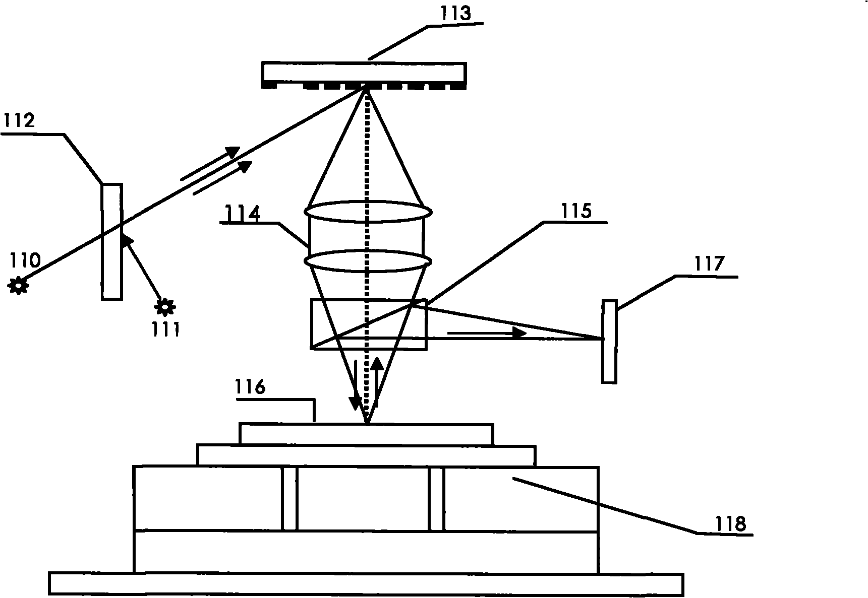
[0020] Such as figure 1 As shown, the maskless lithography alignment system of this embodiment includes an alignment bright light source 111, a first dichroic beam splitter 112, a digital micro mirror device (DMD) 113, a projection objective 114, and a second Dichroic beam splitter 115, silicon wafer 116, photoelectric coupling imaging device 117, workpiece stage 118; the first dichroic beam splitter 112 is located between the exposure light source 110 and the alignment light source 111, and the incident surface of the first dichroic beam splitter 112 receives Expose the exposure light beam of the light source 110, the dichroic dichroic surface of the first dichroic beam splitter 112 receives the alignment light output ...


PUM


Abstract

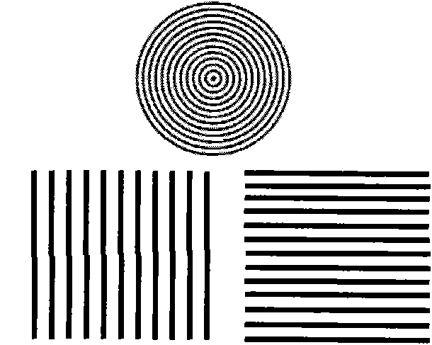
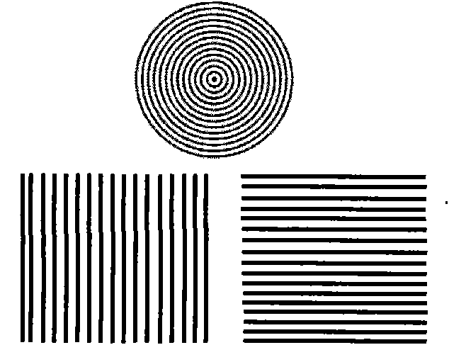
The invention discloses a maskless photoetching alignment system which comprises an alignment light source, a digital micro mirror device, a projection objective, a silicon wafer, a photoelectrical coupling image device, an operating platform, a first dichroic spectroscope and a second dichroic spectroscope, wherein the first dichroic spectroscope receives alignment lights and then reflects the alignment lights to the digital micro mirror device; a computer controls the digital micro mirror device to generate digital gratings; the digital micro mirror device reflects the alignment lights to the projection objective, then the alignment lights are transmitted by the second dichroic spectroscope, and the digital gratings are projected to the silicon wafer and then superposed with the existing mark gratings on the silicon wafer; the alignment lights are reflected by the silicon wafer, then the alignment lights reflected by the second dichroic spectroscope are received by the photoelectrical coupling image device; moire fringe images acquired by the photoelectrical coupling image device are the images generated by the superposition of the digital gratings and the mark gratings on the silicon wafer; and in the computer, the phase information of the moire fringe images acquired by the photoelectrical coupling image device is solved, and the quantities of displacement and rotation of the silicon wafer are solved, and the operating platform is moved so as to realize the maskless photoetching alignment.

Description

Technical field [0001] The invention belongs to the technical field of maskless lithography, and particularly relates to a maskless lithography alignment system based on DMD. Background technique [0002] With the development of micro-nano processing technology, micro-nano devices often require lithography technology and equipment with strong flexibility, high efficiency, speed, and low cost to adapt to small-batch, multi-variety production modes. In the production and processing of devices with continuous surface relief structures, such as micro-optical components, the surface shape is obtained by continuous and accurate modulation of exposure dose, so conventional photolithography technology cannot or is difficult to achieve. In order to produce and process such surface type devices, lithography technology and equipment capable of continuously modulating the exposure dose are required. In addition, traditional lithography methods (ie, electron beam lithography to make masks, a...

Claims


Application Information

Patent Timeline
Patent Type & Authority Applications(China)
IPC IPC(8): G03F7/20G03F9/00
Inventor 马平李艳丽陈铭勇陈磊胡陶
Owner INST OF OPTICS & ELECTRONICS - CHINESE ACAD OF SCI
Learn More