Fiber light-splitting multipath ultraviolet light source

A technology of ultraviolet light source and optical fiber splitter, applied in the field of ultraviolet light source, can solve the problems of not meeting the requirements of ultraviolet spectral process analysis, being susceptible to external interference, large transmission loss, etc., and achieving compact size, reliable performance and simple structure. Effect

Inactive Publication Date: 2011-09-21
上海富科思分析仪器有限公司
View PDF5 Cites 9 Cited by
  • Summary
  • Abstract
  • Description
  • Claims
  • Application Information

AI Technical Summary

Problems solved by technology

However, spectral analysis technology has high requirements on the spectral transmission characteristics of the optical system, especially in the ultraviolet spectral range, because ultraviolet light is easily absorbed during transmission, the transmission loss is large, and the transmission process is easily disturbed by the outside world
However, the traditional optical system design in the prior art cannot meet the requirements of ultraviolet spectroscopic process analysis

Method used


Image

  • Fiber light-splitting multipath ultraviolet light source
  • Fiber light-splitting multipath ultraviolet light source
  • Fiber light-splitting multipath ultraviolet light source

Examples


Embodiment 1

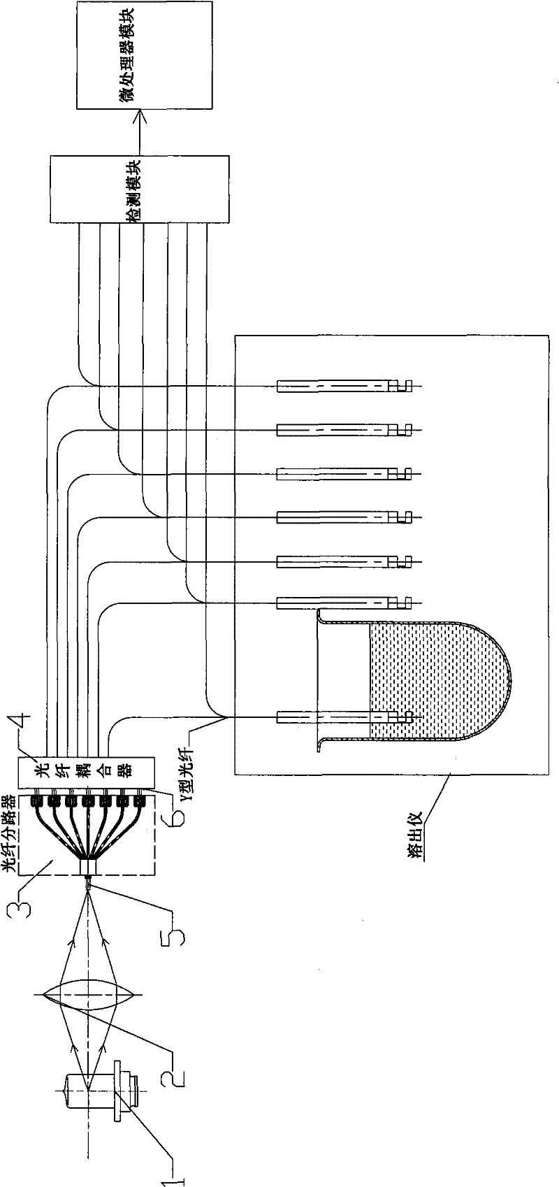
[0028] Such as figure 1 As shown, the optical fiber splitting multi-channel ultraviolet light source of the present invention includes a light source 1 , a lens 2 , a fiber splitter 3 , a fiber coupler 4 , a common end fiber group 5 , and a branch end fiber group 6 .

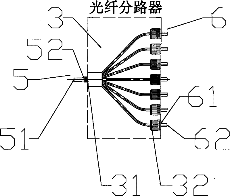
[0029] Such as figure 2 As shown, the common-end optical fiber group 5 includes multiple parallel optical fibers, and the branch-end optical fiber group 6 includes multiple parallel optical fibers. The common-end optical fiber group 5 has an input end 51 and an output end 52 , the optical fiber splitter 3 has an input end 31 and an output end 32 , and the branch-end optical fiber group 6 has an input end 61 and an output end 62 .

[0030] Such as figure 1 and figure 2 As shown, the light source 1 is located at one focal point of the lens 2, the input end 51 of each optical fiber of the common end optical fiber group 5 is located at the other focal point of the lens 2, and the output of each optical fiber of...

Embodiment 2

[0035] The device type and structure of the optical fiber splitting multi-channel ultraviolet light source described in Embodiment 1 remain unchanged, except that the optical fiber splitter 3 has one input end 31 and 2 to 20 output ends 32, correspondingly, the optical fiber The splitting multi-channel ultraviolet light source includes 2 to 20 branch-end fiber groups 6 , and each branch-end fiber group 6 is respectively connected to each output end 32 of the fiber splitter 3 . Therefore, the optical fiber splitting multi-channel ultraviolet light source in this embodiment can divide the light of the light source into 2-20 channels of light.

Embodiment 3

[0037] For the optical fiber splitting multi-path ultraviolet light source of embodiment 2, under the situation that its device type and structure are constant, improve as follows:

[0038] The number of optical fibers contained in the common-end optical fiber group 5 is an integral multiple of the number of optical fibers contained in the branch-end optical fiber group 6 .


PUM

PropertyMeasurementUnit
diameteraaaaaaaaaa
lengthaaaaaaaaaa

Abstract

The invention discloses a fiber light-splitting multipath ultraviolet light source. According to the invention, an ultraviolet silica fiber is used as a multipath light splitter for providing a multipath ultraviolet light source required in an ultraviolet fiber spectroscopy process analysis process. The fiber light-splitting multipath ultraviolet light source comprises a light source, a lens, a fiber splitter, a fiber coupler, a common-end fiber group and a branch-end fiber group, wherein the common-end fiber group comprises a plurality of parallel fibers, the branch-end fiber group comprises a plurality of parallel fibers, the light source is arranged at one focus of the lens, input ends of all fibers of the common-end fiber group are arranged at another focus of the lens, and all the fibers of the common-end fiber group, the fiber splitter, all the fibers of the branch-end fiber group and the fiber coupler are connected with Y-type fibers of a fiber in-situ drug dissolution / release tester in sequence.

Description

technical field [0001] The invention relates to an ultraviolet light source, in particular to an optical fiber splitting multi-channel ultraviolet light source, which can provide multi-channel ultraviolet light sources for multi-channel spectral process analysis. Background technique [0002] In the Chinese patent applications Nos. 200410001756.4 and 200410001179.9 previously applied by the applicant of the present invention, an optical fiber in-situ drug dissolution / release tester is disclosed, which adopts spectral analysis technology and is specially used for the analysis of drug dissolution process. In order to improve work efficiency, multi-channel analysis needs to be performed simultaneously. However, spectral analysis technology has high requirements on the spectral transmission characteristics of the optical system, especially in the ultraviolet spectral range, because ultraviolet light is easily absorbed during the transmission process, the transmission loss is lar...

Claims


Application Information

Patent Timeline
Patent Type & Authority Applications(China)
IPC IPC(8): F21V13/02F21V5/04F21V8/00G01N21/25
Inventor 刘欢李华西李翔王良玉熊海江
Owner 上海富科思分析仪器有限公司
Why Eureka
Try Eureka