Processing process of cold oil pipe

A processing technology and oil pipe technology, applied in the field of cold oil pipe processing technology, can solve the problems of high material cost, poor heat dissipation efficiency, complicated manufacturing process, etc., and achieve the effect of low material cost, low manufacturing cost and easy implementation

Inactive Publication Date: 2011-09-14
东莞吉旺汽车零件有限公司
View PDF5 Cites 5 Cited by
  • Summary
  • Abstract
  • Description
  • Claims
  • Application Information

AI Technical Summary

Problems solved by technology

Its disadvantages are complex manufacturing process, high material cost and poor heat dissipation performance.

Method used


Image

  • Processing process of cold oil pipe
  • Processing process of cold oil pipe
  • Processing process of cold oil pipe

Examples


Embodiment Construction

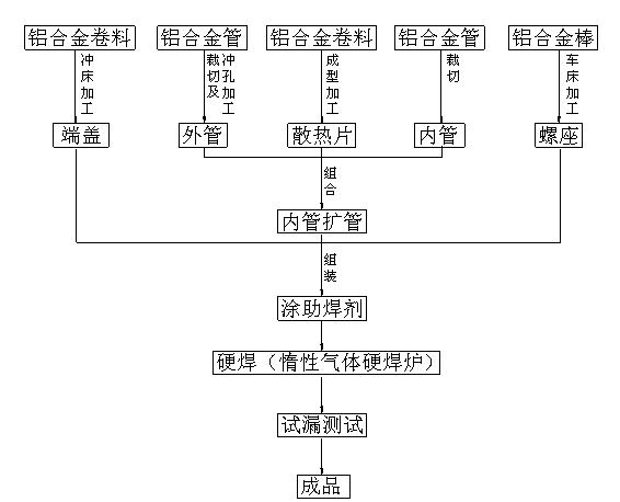
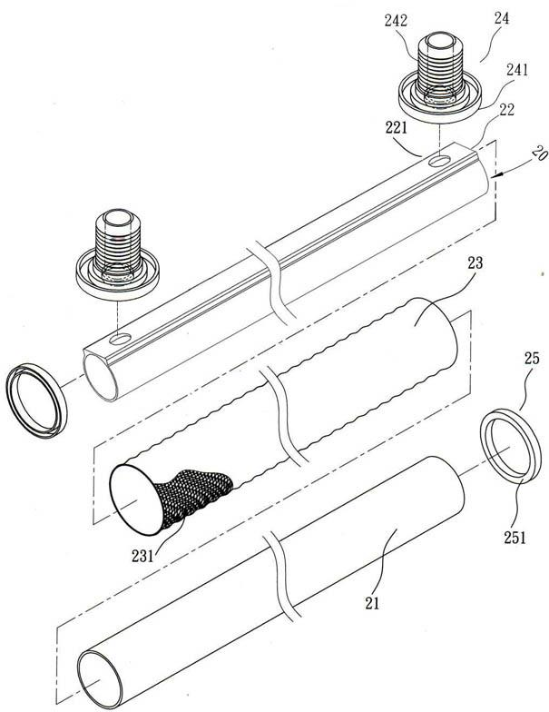
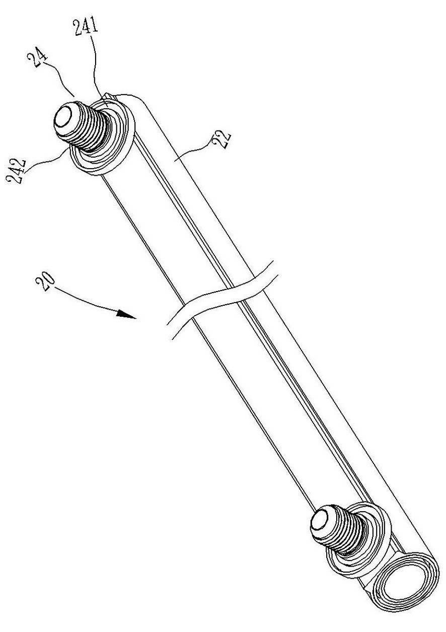
[0026] Such as Figure 1 to Figure 4 As shown, a kind of cold oil pipe processing technology of the present invention is composed of a circular hollow inner and outer pipe 21, 22 and an oil cooling pipe 20 composed of a cooling fin 23 interposed therebetween. The inner and outer pipes 21, 22 It is an aluminum tube formed by a cutting punching machine, and the two upper ends of the outer tube 22 are oppositely provided with through holes 221. The heat sink 23 is formed by processing an aluminum coil into a number of heat dissipation holes 231 forming a vortex surface. Improve heat dissipation, and set two screw seats 24 that match the through holes 221 at both ends of the outer tube 22. The two screw seats 24 are made of aluminum rods that are processed by a lathe to form a shape, and a concave shape is provided at the bottom of the screw seat 24 The welded portion 241 of the welding part and the assembly end 242 protruding from a hollow external thread, and an end cap 25 with ...


PUM


Abstract

The invention relates to a processing process of a cold oil pipe, comprising the following steps of: manufacturing an inner pipe and an outer pipe from aluminum materials, and clamping a heat-radiating fin manufactured from the aluminum materials and provided with a plurality of heat-radiating holes between the inner pipe and the outer pipe; then matching with an oil cooling pipe with lighter weight, which is integrally combined in an inner pipe expanding manner; processing a plurality of screw seats and an end cover through the aluminum materials; and arranging a welding part and projecting a hollow combining end on the bottom end of the screw seat to form an oil inlet and an oil outlet which are communicated with an oil inlet pipe and an oil outlet pipe with through holes. The invention has the advantages of simplified manufacturing process, lower manufacturing cost, lower material cost and lighter product by being manufactured from the aluminum materials, higher heat-radiating efficiency, sufficient temperature reduction of engine oil, sufficient engine tractive force, reasonable conception, easy implementation, high practicability, popularization application, and the like.

Description

technical field [0001] The invention relates to a cold oil pipe processing technology. Background technique [0002] The traditional oil cooling tube manufacturing method is generally as follows: take two red copper tubes with different diameters and process them into an outer tube by cutting and punching, and then expand the tube into an inner tube by cutting the end, and then cooperate with a brass coil processing The formed heat sink is tightly sealed in it, and there are through holes at both ends near the top of the outer tube, so that the two ends of the inner and outer tubes are connected and combined by welding, and then the car is turned into yellow. The two screw seats processed by copper rods are coated with flux and welded to the through holes at both ends of the outer tube by silver welding. The heat sink is in a tightly bonded state, and then the finished product can be completed through the steps of pickling and degreasing cleaning, leak testing, and drying...

Claims


Application Information

Patent Timeline
Patent Type & Authority Applications(China)
IPC IPC(8): B23P15/00B23K1/008
Inventor 蔡兆文
Owner 东莞吉旺汽车零件有限公司
Why Eureka
Try Eureka