
Multi-station machine vision imaging detection method and system based on graphics processor

A graphics processor and machine vision technology, applied in closed-circuit television systems, processor architecture/configuration, liquid level indicators for physical variable measurement, etc., can solve the problem of increasing the size and cost of machine vision detection equipment, and the detection time of a single computer Difficult to control, difficult to achieve stability, reliable detection and other issues, to achieve the effect of improving system stability and reliability, reducing system complexity, and low cost

Inactive Publication Date: 2011-08-31
HUNAN UNIV
View PDF7 Cites 27 Cited by
  • Summary
  • Abstract
  • Description
  • Claims
  • Application Information

AI Technical Summary

Problems solved by technology

[0005] 1. Complicated and large-scale machine vision equipment
Multiple stations require multiple computers, which increases the volume and cost of machine vision inspection equipment;
[0006] 2. It is difficult to synchronize the detection of multiple stations
Since each computer works independently, the detection system needs to synchronize multiple detection processes. Since the detection time of a single computer is difficult to control, the current system structure increases the difficulty of real-time synchronization of each station, and it is difficult to realize the stability of multiple stations for the same product. Reliable detection;
[0007] 3. It is difficult to realize the coordinated control of the whole machine
[0008] Due to the above problems, most of the current high-speed automated production line machine vision inspection equipment is limited to the detection of a single station; the multi-station inspection system is extremely complex and has poor stability; the multi-station machine vision quality inspection system is still one of the current machine vision inspection equipment. unresolved technical problems

Method used


Image

  • Multi-station machine vision imaging detection method and system based on graphics processor
  • Multi-station machine vision imaging detection method and system based on graphics processor
  • Multi-station machine vision imaging detection method and system based on graphics processor

Examples


Embodiment Construction

[0044] The present invention will be further described in detail below in conjunction with the accompanying drawings and specific embodiments.

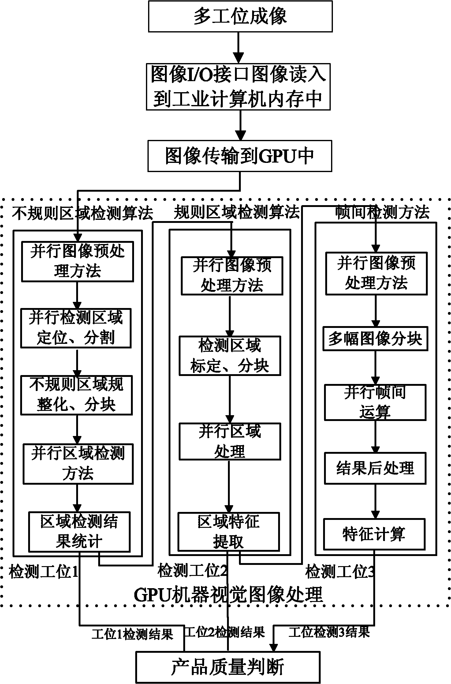
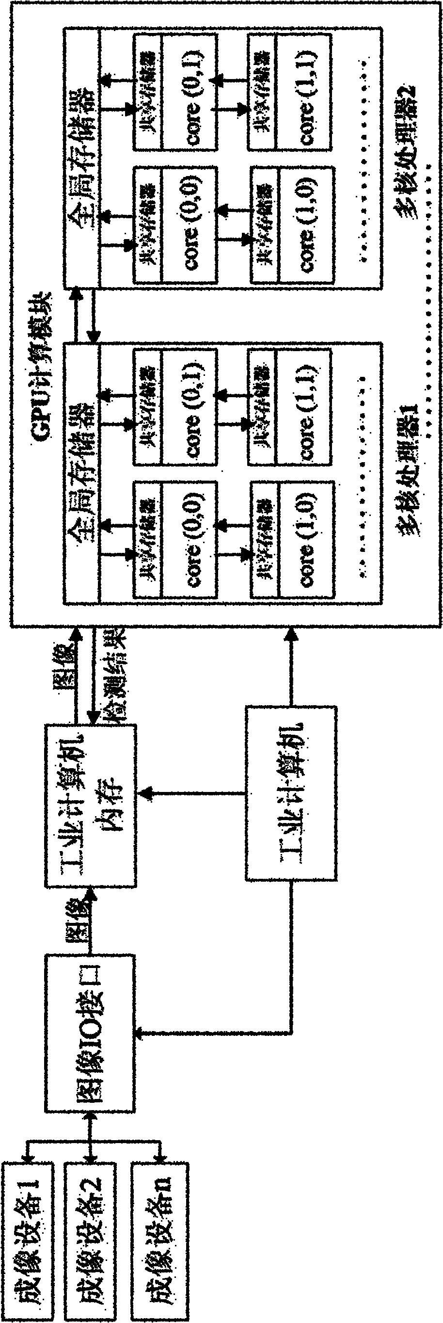
[0045] Graphics Processing Unit (GPU), referred to as GPU, is a processor for large-scale parallel processing of graphics and images. It is usually used as a slave device of a general-purpose processor to process and display graphics and images in real time. In the GPU, there are multiple multi-core processors, and each multi-core processor contains multiple processing units. Each processing unit can run multiple threads at the same time. This large-scale parallel structure is very suitable for real-time image processing, and has Hundreds of gigabytes per second of communication bandwidth, hundreds of billions of computing power. The present invention adds several GPU modules on the basis of the traditional machine vision inspection equipment, utilizes the large-scale graphics and image processing capability of the GPU to perform para...


PUM


Abstract

The invention relates to a multi-station machine vision imaging detection method and a system based on the graphics processor. The method comprises following steps: arranging an imaging device on each detection station, controlling more than one image I / O interfaces through the industrial computer, and transmitting the image obtained from imaging device connected with each I / O interface of the image to the industrial computer memory; transmitting the image to GPU calculating modules by the industrial computer which can do real-time processing to image obtained from each detection station and transmit the result to the industrial computer. The system comprises an industrial computer, more than one GPU calculating modules, more than one image I / O interfaces, more than one imaging system, a multi-station position detecting device, a whole machine time schedule controller, a winkling controller and a winkling device. The invention has advantages of simple and compact structure, low cost, high integrated level, good stability, reliability and versatility, etc.

Description

technical field [0001] The invention mainly relates to the technical field of product machine vision quality inspection and control on an automated production line, in particular to a high-speed real-time image processing method and a detection system applied to multi-station machine vision quality inspection on a high-speed automated production line. Background technique [0002] At present, on a high-speed automated production line, it is usually necessary to perform multi-station quality inspection on a certain product. Multi-station quality inspection can detect more parameters, such as detection of different types of foreign objects at different stations in liquid product quality inspection, liquid level inspection, appearance quality inspection, etc.; at the same time, multi-station inspection can improve The accuracy of quality inspection, such as multiple inspections of inspection objects at multiple stations can improve the accuracy of inspection of unqualified prod...

Claims


Application Information

Patent Timeline
IPC IPC(8): G01N21/88G01F23/22H04N7/18G06T1/20
Inventor 王耀南陈铁健熊路吴成中张辉周博文葛继杨双周叶博
Owner HUNAN UNIV
Learn More