
Pressure drilling device for a drill stem and a using method thereof

A drilling device and drill pipe technology, which is applied to drill pipes, drill pipes, drilling equipment, etc., can solve the problems that the pressure cannot be balanced, the drill pipe is maintained, and the sealing effect is not good, so as to ensure the sealing effect and ensure the pressure balance. , The effect of drilling is convenient and quick

Inactive Publication Date: 2013-02-20
SOUTHWEST PETROLEUM UNIV
View PDF10 Cites 0 Cited by
  • Summary
  • Abstract
  • Description
  • Claims
  • Application Information

AI Technical Summary

Problems solved by technology

However, the arc-shaped sealing ring uses a general arc-shaped or oval sealing ring to seal around the drill pipe opening. The end face of the sealing ring is a planar structure, and the seal between the end face and the outer wall of the drill pipe, The end face of the sealing ring is bonded to the outer wall of the drill pipe through pressure, and the sealing ring is deformed for sealing. The sealing effect of this sealing structure is not good under the high pressure state of 70MPa and above, and it is easy to leak
The pressurized drilling device of this patent is equipped with too many valve parts, which makes the outer mass of the hoop heavier, which will generate a large bending moment, deform the passage of the drill bit in advance and retreat, and often cause difficulties in the axial feeding of the drilling machine, etc. phenomenon; and the pressurized drilling device did not take any method to maintain the pressure balance inside and outside the drill pipe during the drilling process. Because the drilling fluid circulation channel flowing through the drill pipe was blocked, the pressure inside the drill pipe was extremely high, and the drill There is a large pressure difference inside and outside the rod, and the pressure cannot be balanced. At the moment when the drilling device is about to complete the drilling of the drill rod, the high-pressure fluid inside the drill rod will impact the drilling machine through the drilling hole, which will Damage the drilling machine by puncturing the drill pipe
Moreover, this patent uses manual control of the feed, which is time-consuming and labor-intensive, and the drill pipe cannot be processed conveniently and quickly. Moreover, the drilling fluid circulation channel in this patent is single, and the structure is not flexible enough for multiple purposes.

Method used


Image

  • Pressure drilling device for a drill stem and a using method thereof
  • Pressure drilling device for a drill stem and a using method thereof
  • Pressure drilling device for a drill stem and a using method thereof

Examples


Embodiment Construction

[0050] All features disclosed in this specification, or steps in all methods or processes disclosed, may be combined in any manner, except for mutually exclusive features and / or steps.

[0051] Any feature disclosed in this specification (including any appended claims, abstract and drawings), unless expressly stated otherwise, may be replaced by alternative features which are equivalent or serve a similar purpose. That is, unless expressly stated otherwise, each feature is one example only of a series of equivalent or similar features.

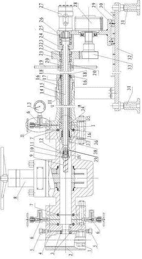
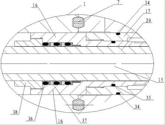
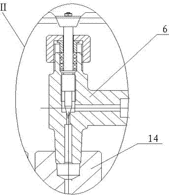
[0052] Such as Figure 1 to Figure 6 As shown, the pressurized drilling device for drill pipes of the present invention is connected with the drill pipe by using a Huff type hoop. The shoulder hex bolt 1 is fastened and fixedly connected, wherein the anti-skid hoop 2 and the sealing hoop 4 are matched with the outer wall of the drill pipe, so the inner walls of the anti-skid hoop 2 and the sealing hoop 4 are arc-shaped structures, and the sea...


PUM


Abstract

The invention discloses a pressure drilling device for a drill stem and a using method thereof, which belong to the technical field of pressure drilling. In the pressure drilling device for the drill stem, a sealing hoop is connected with a meter flange; the meter flange is provided with a pressure inlet and is connected with a pressure gage and a valve; the valve is connected with a hydraulic drilling device; and the hydraulic drill device is connected with a reciprocating motion mechanism. The using method of the pressure drilling device for the drill stem comprises the following steps of: 1, assembling; 2, assembling on the drill stem; 3, making a reciprocation hydraulic motor work and driving the drill stem to feed cutter; 4, making a rotating hydraulic motor to work, balancing the pressure difference between the inside and the outside of the drill stem when the high pressure enters an axial airtight chamber of the valve; 5, drilling and opening pores by using the drill stem; and 6, making the hydraulic drilling device return in situ, and building a new drilling fluid circulation channel. By the pressure drilling device for the drill stem and the using method thereof, the high pressure of more than or equal to 70 MPa can be withstood, and safe channels for subsequent pressure well boosting are provided.

Description

technical field [0001] The invention relates to a pressure drilling technology, in particular to a pressure drilling technology for a drill pipe. Background technique [0002] In oil and gas exploration and development well control work, if the drilling fluid circulation channel is blocked, the weighted mud cannot effectively enter the drill pipe, and the liquid column pressure and formation pressure cannot be balanced, which will induce blowout out of control accidents. As an indispensable tool in drilling operations, drill pipe plays the role of providing power to the bottom of the well and establishing a drilling fluid circulation channel at the same time. Since the cock valve above the drill pipe cannot be opened or the drilling fluid circulation channel flowing through the drill pipe is blocked after the shear ram cuts the drill pipe, after the channel is cut off, if the new drilling fluid circulation channel cannot be established in time and effectively, then More ser...

Claims


Application Information

Patent Timeline
Patent Type & Authority Patents(China)
IPC IPC(8): E21B17/04E21B29/00E21B17/00E21B21/10
Inventor 刘清友严永发王国荣林发权王云海刘丹丹
Owner SOUTHWEST PETROLEUM UNIV
Learn More