
Laser-impact strengthening treatment method for steel welded joint of X70 pipeline

A laser shock strengthening and welding joint technology, applied in heat treatment furnaces, heat treatment equipment, furnaces and other directions, can solve the problems of reducing stress corrosion and hydrogen-induced cracking of pipeline steel welded joints, reducing mechanical properties of welded joints, and reducing strength of welded joints, etc. Achieve the effect of improving the resistance to H2S stress corrosion, eliminating the residual tensile stress caused by cracking, and improving the surface microhardness

Inactive Publication Date: 2011-07-20
JIANGSU POLYTECHNIC UNIVERSITY
View PDF0 Cites 13 Cited by
  • Summary
  • Abstract
  • Description
  • Claims
  • Application Information

AI Technical Summary

Problems solved by technology

The residual stress caused by welding has a significant impact on the mechanical properties of materials. High residual tensile stress can lead to cracks inside the structure, which reduces the H resistance of pipeline steel welded joints. 2 S stress corrosion and hydrogen induced cracking capability
[0003] X70 pipeline steel is generally formed from plate to pipe by submerged arc automatic welding. Due to the input of a large amount of heat source during the welding process, welding residual stress is prone to occur, which reduces the mechanical properties of the welded joint. At the same time, the filler material and the materials on both sides of the weld After melting and recrystallization, the as-cast structure is finally formed on the surface of the welded joint, which is prone to welding defects such as pores and shrinkage, resulting in a decrease in the strength of the welded joint, which is generally only 50% to 60% of the strength of the base material. Improving the performance of welded joints by means of pellets, ultrasonic waves, explosions, rolling, hammering, etc.

Method used


Image

  • Laser-impact strengthening treatment method for steel welded joint of X70 pipeline
  • Laser-impact strengthening treatment method for steel welded joint of X70 pipeline
  • Laser-impact strengthening treatment method for steel welded joint of X70 pipeline

Examples


Embodiment Construction

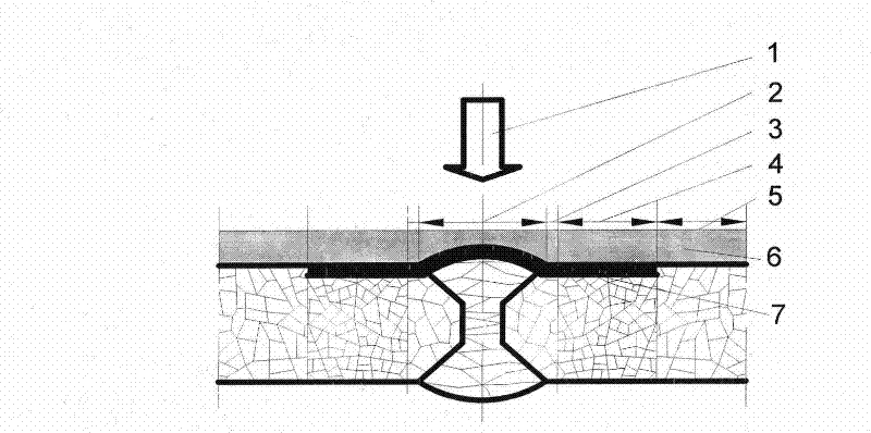
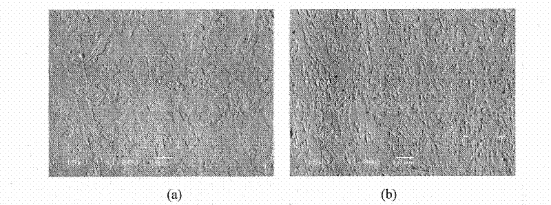
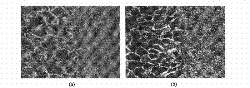
[0015] Using laser shock waves to strengthen the surface of X70 steel welded joints, such as figure 1 As shown, the laser pulse width is 22ns-23ns, the wavelength is 1.054μm, the amplified spontaneous emission pulse width is 1μs, the output laser is focused by a focusing system with a focal length of 2m, the diameter of the focused spot is 5mm-8mm, and the laser pulse power is about 2.0×10 9 W. With 0.1mm aluminum foil as the absorbing layer and 2mm thick water as the constraining layer, laser shock is performed on the surface of the welded joint of pipeline steel. After laser shock treatment, the microstructure of welded joints changed significantly, and the surface grains of welded joints were refined, such as figure 2 shown. The surface layer undergoes severe plastic deformation, and the degree of deformation gradually decreases with the increase of depth, as shown in image 3 As shown, during the laser shock process, the deformation gradually develops from the surface ...


PUM


Abstract

The invention relates to a laser-impact strengthening treatment method for a steel welded joint of an X70 pipeline, wherein an energy absorption layer and a restraint layer are arranged on the surface of the steel welded joint of the X70 pipeline in sequence. The laser-impact strengthening treatment method is characterized in that during laser-impact strengthening treatment, the laser pulse width is 22ns-23ns, the wavelength is 1.054mu m, the amplification spontaneous radiation pulse width is 1mu s, a focusing system with the focal length of 2m for outputting laser is used for focusing, the focusing spot diameter is 5mm-8mm, the laser pulse power is about 2.0*109W, and the spot overlapping area on the surface of the welded joint is greater than 60%. After laser-impact strengthening, the surface of the steel joint of the pipeline generates plastic deformation, grain refinement and residual compressive stress, thus effectively improving the H2S stress corrosion resistance and hydrogen induced cracking resistance of the steel welded joint of the pipeline.

Description

technical field [0001] The invention relates to a strengthening treatment method on the surface of X70 pipeline steel welded joints by using laser shock waves, in particular to a method for producing grain refinement and residual compressive stress on the surface of X70 pipeline steel welded joints by laser shock treatment, which improves the H resistance of pipeline steel welded joints. 2 The performance of S stress corrosion and hydrogen-induced cracking belongs to the field of material surface modification treatment. Background technique [0002] The service conditions of X70 pipeline steel are mostly wet soil and desert environment, and the transmission medium contains more acidic substances such as H2S. Corrosion is a key factor affecting the reliability and service life of the pipeline system. Because the welding part of the high-pressure transmission pipeline, especially the welding part of the laying pipeline, is a frequent location of failure accidents. The residua...

Claims


Application Information

Patent Timeline
IPC IPC(8): C21D9/50C21D1/09
Inventor 孔德军张永康王文昌周朝政裴峻峰胡爱萍
Owner JIANGSU POLYTECHNIC UNIVERSITY
Learn More