
Calibrating device of sound phase instrument

A calibration method and calibrator technology, which is applied in the field of phaser calibration, can solve the problems of positioning influence, time-consuming and labor-intensive, and high cost, and achieve the effects of accurate objectivity, accurate calibration, and small size

Inactive Publication Date: 2013-09-11
INST OF ACOUSTICS CHINESE ACAD OF SCI
View PDF1 Cites 0 Cited by
  • Summary
  • Abstract
  • Description
  • Claims
  • Application Information

AI Technical Summary

Problems solved by technology

However, due to the fact that there may be some differences among the array elements on the microphone array during the manufacturing process, this error will have a serious impact on the positioning, so the generated acoustic image needs to be calibrated
[0003] The traditional acoustic calibration method can only calibrate the measurement characteristics of a single array element, which can eliminate the difference between the microphone array elements, thereby ensuring the correctness of the sound image generated by the panning instrument. Imaging image deviation cannot be verified
When the number of microphone array elements increases, the traditional one-by-one calibration method is time-consuming and laborious; there is another method for array calibration, which is to calibrate the entire array with a fixed reference sound source detection method, and use a point sound source at a specific position Sound, and then verify and calibrate the sound. This process needs to be carried out in a specific device. The device is an acoustic drum, and the wall of the drum is completely filled with sound-absorbing materials of uniform thickness, so the device is very bulky and cumbersome. Portable and expensive, on the other hand, it does not involve the error calibration of acoustic positioning and optical positioning; patent 200810213962.X proposes a calibration method to calculate the audio signal and noise received by each microphone array element The acoustic correlation of the signal, when the acoustic correlation exceeds the set threshold, the average gain is calculated to adjust the gain of each channel to achieve the purpose of calibration, but this method has no specific and feasible standards when setting the correlation threshold As a basis, it is very difficult to select the correlation threshold, and the patent does not involve the error verification of acoustic positioning and optical positioning

Method used


Image

  • Calibrating device of sound phase instrument
  • Calibrating device of sound phase instrument
  • Calibrating device of sound phase instrument

Examples


Embodiment 1

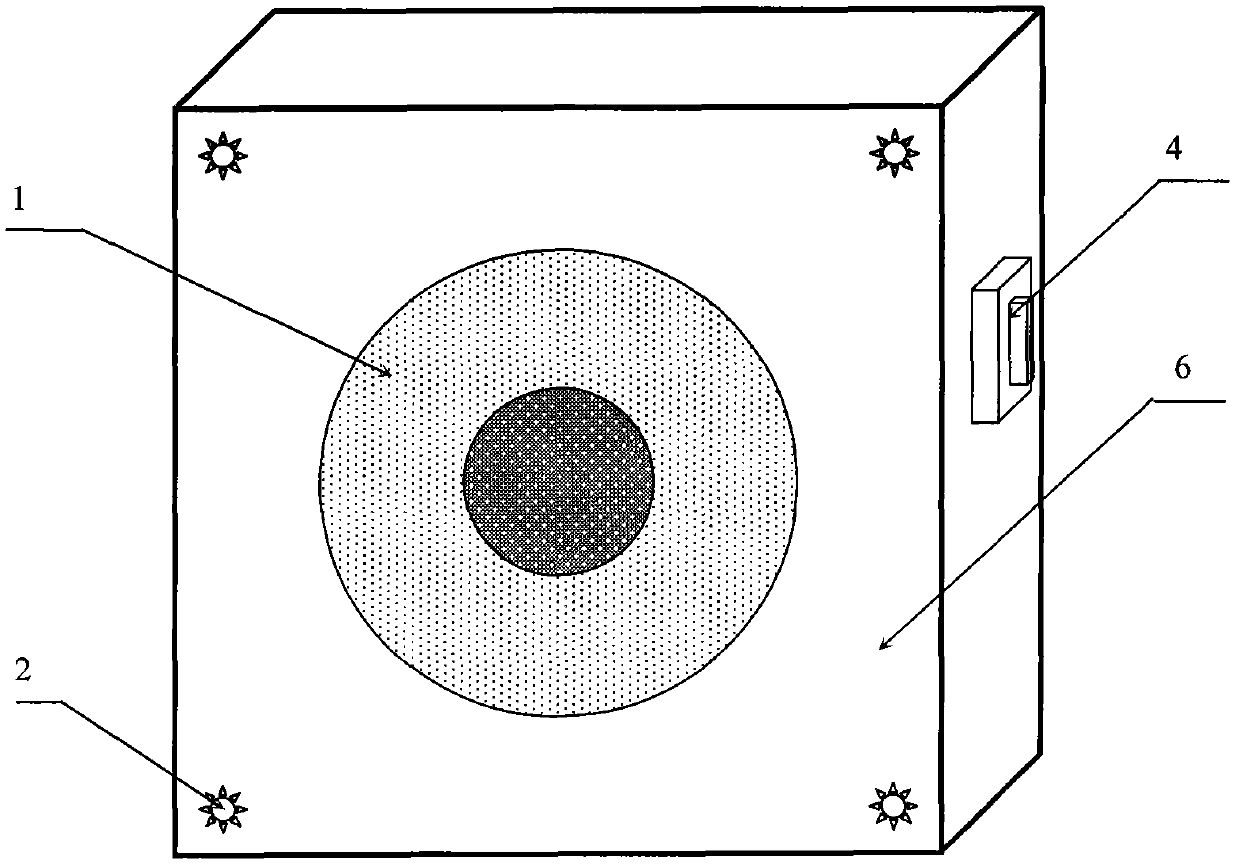
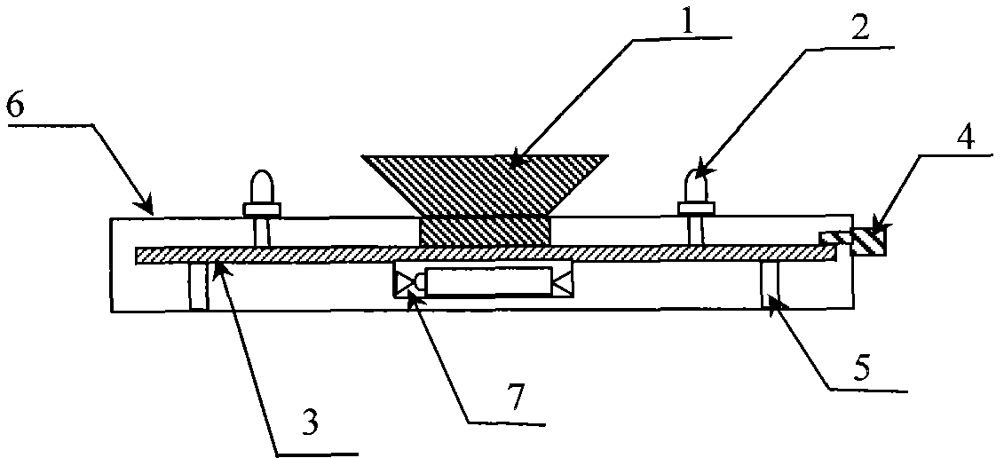
[0041] The present embodiment is an acoustic phase instrument calibrator equipped with a calibration light source composed of 4 LED light-emitting diodes, such as Figure 1~2 shown. The structure includes: a single-frequency calibration sound source 1, a calibration light source 2, a circuit board 3, a control switch 4, a bracket 5, a casing 6 and a battery box 7.

[0042] Such as figure 1 and 2 As shown, the circuit board 3 is fixedly connected to the housing 6 through four brackets, the battery box 7 is installed on the back of the circuit board 3, and the four LED light-emitting diodes 2 of the single-frequency calibration sound source 1 and the calibration light source are welded on the circuit board 3 On, the switch 4 is welded on the circuit board 3 to control the work of the single-frequency verification sound source 1 and the verification light source 2 .

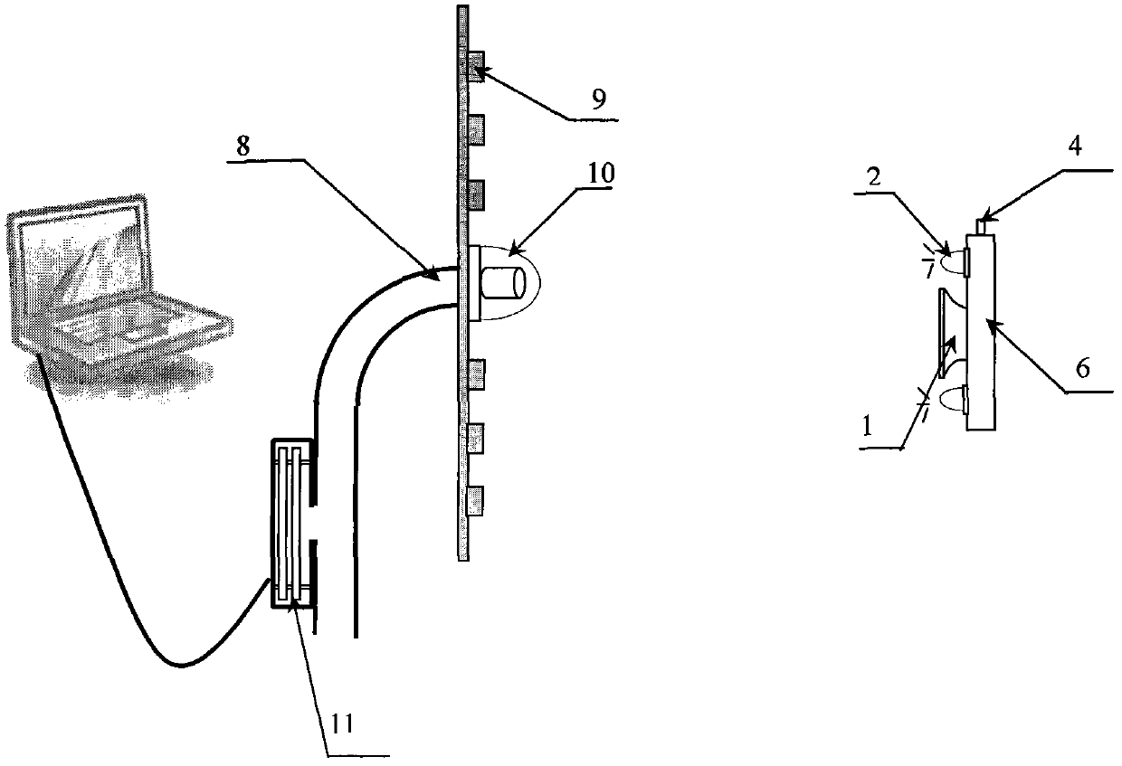
[0043] Such as image 3 As shown, when the switch 4 is pressed, the calibrator of the sound phase instrument ...

Embodiment 2

[0056] This embodiment is basically the same as Embodiment 1, except that the calibration light source in this embodiment has only one LED light-emitting diode, so that the volume of the calibrator is smaller and the structure is simpler, such as Figure 5 shown. In this way, the correction calculation process is also simplified, using the position of the LED light-emitting diode (x D ,y D ) as the standard position of the single-frequency calibration sound source, and calculate the x-axis offset correction coefficient L x and the y-axis offset correction factor L y The formulas of are shown in the following formulas (7) and (8):

[0057] L x =x D -X (7)

[0058] L y =y D -Y (8)

[0059] The coordinates (x Dj ,y Dj )j=1,2,...,N, j represents the label of the calibration position of the calibrator, that is, the four positions of up, down, left, and right. Calculate the x-axis scaling correction factor K x and the y-axis scaling correction factor K y The formula of...


PUM


Abstract

The invention relates to a calibrating device of a sound phase instrument, which includes a single frequency calibrating sound source (1) used for providing a standard sound source and a calibrating sound source (2); the calibrating sound source (2) includes a plurality of LEDs (light-emitting diodes), and is used for providing the standard sound source to position the single frequency calibrating sound source (1); one LED (light-emitting diode) is used for providing the standard sound source, and the horizontal distance between the LED (light-emitting diode) and the single frequency calibrating sound source (1) is not larger than 5 mm; or more LEDs (light-emitting diodes) are used for providing the standard sound source, and are respectively, uniformly and symmetrically mounted on peaks of a regular geometric polygon which takes the single frequency calibrating sound source (1) as the center. The calibrating device of the sound phase instrument adopts the acousto-optic combined calibration, overcomes the defect that the traditional calibrating device adopts the sound for single calibration, and gives full play to the advantage that the optical signal calibration is accurate.

Description

technical field [0001] The invention relates to the field of acoustic measurement, in particular, the invention relates to a method for calibrating an acoustic phaser. Background technique [0002] Panorama positioning is to use its microphone array acoustic imaging technology to detect sound information based on the array elements distributed according to certain rules, convert it into digital signal after collection, input it into the digital signal processor, and locate multiple sound sources after calculation The instrument, which uses beamforming technology, has the functions of realizing sound source localization, sound field detection, suppressing background noise interference, etc. However, since the array elements on the microphone array may have certain differences during manufacturing and processing, this error will have a serious impact on positioning, so it is necessary to calibrate the generated acoustic image. [0003] The traditional acoustic calibration met...

Claims


Application Information

Patent Timeline
Patent Type & Authority Patents(China)
IPC IPC(8): H04R29/00
Inventor 杨亦春滕鹏晓
Owner INST OF ACOUSTICS CHINESE ACAD OF SCI
Learn More