Position detecting device and signal processing device and method thereof
A signal processing device and detection device technology, which is applied in the direction of measuring devices, using electric/magnetic devices to transmit sensing components, converting sensor outputs, etc., can solve the problem of difficult to obtain accurate position signal θ, and reduce circuit reliability and stability , anti-vibration and shock ability are not strong, etc., to improve the original signal quality, reduce the effective area, and facilitate the installation process
- Summary
- Abstract
- Description
- Claims
- Application Information
AI Technical Summary
Problems solved by technology
Method used
Image


Examples
Embodiment 1
[0081] Embodiment 1 of the present invention provides a position detection device in which the first column of magnetic induction elements is provided with two magnetic induction elements 308 and the second column of magnetic induction elements is provided with three magnetic induction elements 309 .
[0082] Figure 7 It is a structural diagram of the first magnetic steel ring, the magnetic permeable ring and the magnetic induction element in Embodiment 1 of the present invention; Figure 8 It is a diagram showing the magnetization sequence of the first magnetic steel ring and the positional relationship with the magnetic induction element in Embodiment 1 of the present invention. There are 2 magnetic induction elements 308 in the first column corresponding to the first magnetic steel ring 302, i.e. m=2, with H 1 and H 2 Indicates that the two magnetic sensing elements H 1 and H 2 They are respectively placed in the two gaps corresponding to the magnetic permeable ring 30...
Embodiment 2
[0102] Embodiment 2 of the present invention provides a schematic diagram of four magnetic induction elements corresponding to the first magnetic steel ring 302 .
[0103] Figure 12It is a structural schematic diagram of the first magnetic steel ring Hall element, the magnetic permeable ring, and the magnetic induction element in the position detection device of Embodiment 2 of the present invention; Figure 13 It is a diagram of the magnetization sequence of the first magnetic steel ring and the position relationship with the magnetic induction element in the second embodiment of the present invention.
[0104] Such as Figure 12 As shown, there are 4 magnetic induction elements 308 corresponding to the first column of the first magnetic steel ring 302, that is, m=4, and H 1 、H 2 、H 3 and H 4 Indicates that the two magnetic sensing elements H 1 、H 2 、H 3 and H 4 They are respectively placed in the four gaps corresponding to the first magnetic permeable ring 304 . T...
Embodiment 3
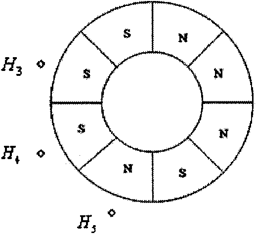
[0108] Embodiment 3 of the present invention provides a structural diagram in which three magnetic induction elements are provided corresponding to the first magnetic steel ring.
[0109] Figure 15 It is a structural schematic diagram of the first magnetic steel ring Hall element, the magnetic permeable ring, and the magnetic induction element of Embodiment 3 of the present invention; Figure 16 It is the magnetization magnetic sequence of the first magnetic steel ring and the position relationship diagram with the magnetic induction element in the embodiment 3 of the present invention;
[0110] Such as Figure 15 As shown, there are three magnetic induction elements 308 corresponding to the first magnetic steel ring 302 in the first column, that is, m=3, and H 1 、H 2 and H 3 Indicates that the two magnetic sensing elements H 1 、H 2 and H 3 They are respectively placed in the three gaps corresponding to the first magnetic permeable ring 304 . The second row of magneti...
PUM
 Abstract
Description
Claims
Application Information
 - R&D
- Intellectual Property
- Life Sciences
- Materials
- Tech Scout
- Unparalleled Data Quality
- Higher Quality Content
- 60% Fewer Hallucinations
Browse by: Latest US Patents, China's latest patents, Technical Efficacy Thesaurus, Application Domain, Technology Topic, Popular Technical Reports.
© 2025 PatSnap. All rights reserved.Legal|Privacy policy|Modern Slavery Act Transparency Statement|Sitemap|About US| Contact US: help@patsnap.com