
Low-energy-consumption method for separating ilmenites from tailings in iron choosing plant

A technology for iron concentrators and ilmenite, which is applied in the field of ilmenite separation, can solve the problems of ineffective dispersion of selected materials in separation tanks, low quality of magnetic concentrate products, and restrictions on industrial application, so as to prevent heavy Mineral deposition, advanced permanent magnetic circuit design, and the effect of improving ore feeding efficiency

Active Publication Date: 2014-01-08
CHANGSHA RES INST OF MINING & METALLURGY
View PDF7 Cites 5 Cited by
  • Summary
  • Abstract
  • Description
  • Claims
  • Application Information

AI Technical Summary

Problems solved by technology

Due to the relative simplification of the feeding method of the traditional permanent magnetic cylinder type magnetic separator, the selected materials cannot be effectively dispersed in the sorting tank, resulting in a relatively low recovery rate; at the same time, due to the magnetic linkage or high background field strength, the Inclusions make the quality of magnetic concentrate products low, which limits the industrial application of permanent magnet drum type magnetic separators

Method used


Image

  • Low-energy-consumption method for separating ilmenites from tailings in iron choosing plant
  • Low-energy-consumption method for separating ilmenites from tailings in iron choosing plant
  • Low-energy-consumption method for separating ilmenites from tailings in iron choosing plant

Examples


Embodiment

[0035] a kind of like Figure 5 Shown the method for the low energy consumption separation ilmenite of the present invention from iron dressing plant tailings, it is mainly aimed at certain ground iron dressing plant tailings, comprises the following steps:

[0036] (1) Permanent magnetic cylinder type strong magnetic separation:

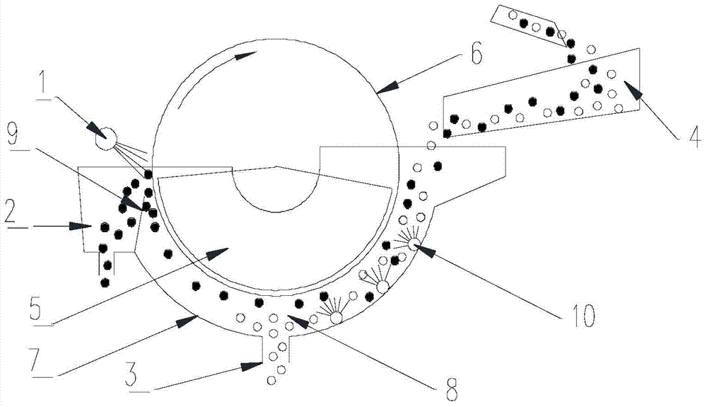
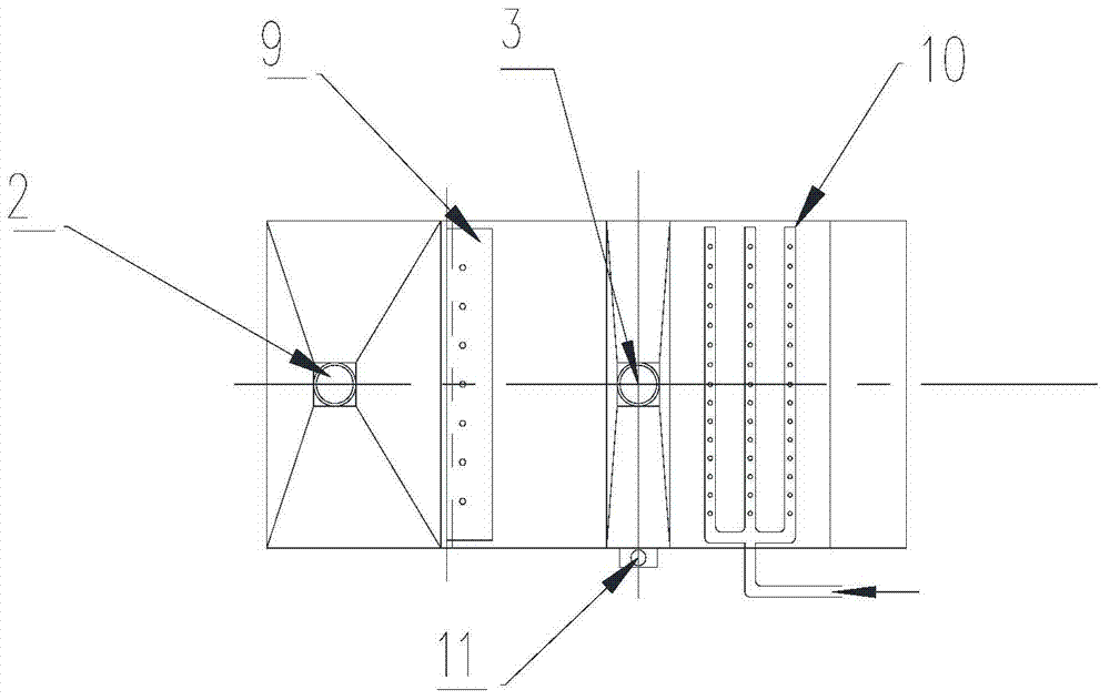
[0037] Using the tailings of the iron dressing plant as raw material, first use such as Figure 1 ~ Figure 3The shown permanent magnetic cylinder type medium magnetic separator sorts the raw material (the magnetic field strength is 8000GS), the non-magnetic material is directly discharged as magnetic separation tailings, and the medium magnetic separation concentrate as magnetic material enters the next step; through the present invention The pre-selection and tailing treatment of the permanent magnetic cylinder type magnetic separator greatly reduces the amount of material that needs to be ground again for "the tailings of the iron processing plan...


PUM


Abstract

The invention discloses a low-energy-consumption method for separating ilmenites from tailings in an iron choosing plant. The method comprises the following steps: firstly, by taking the tailings in the iron choosing plant as raw materials, separating the tailings by using a permanent magnet drum-type mediate-intensity magnetic separator; discharging non-magnetic materials directly taken as magnetic separation tailings; next, grinding mediate magnetic separation concentrates taken as magnetic materials under the conditions that the monomer separation of the ilmenites is effectively realized while the grinding concentrates, the fineness of which is controlled as -75mu m, account for 75% to 95%; performing low-intensity magnetic separation on the mediate magnetic separation concentrates by using a low-intensity magnetic separator so as to separate iron concentrates and lead the rest of mineral materials to enter the next step; performing rough separation on the rest of mineral materials and then performing fine separation on the concentrates for multiple times after the rough separation so as to obtain ilmenite concentrates; performing sweeping separation on the tailings after the rough separation; combining the useful mineral materials for multiple times after the sweeping separation; returning the tailings after the fine separation into a rough separation process; and finally discharging the tailings which are subjected to the sweeping separation are taken as the ilmenites. The method is simple in process, reasonable in magnetic path design, uniform in magnetic field distribution, high in metal recovery rate and good in separation quality.

Description

technical field [0001] The invention relates to a method for sorting ilmenite, in particular to a method for sorting ilmenite from tailings of an iron concentrator. Background technique [0002] Most of my country's ilmenite resources are symbiosis of titano-magnetite and ilmenite. The traditional vanadium-titanium magnetite process is mostly to select iron first, titano-magnetite enters iron concentrate, and then selects titanium, and ilmenite enters titanium concentrate. After many years of research on vanadium-titanium magnetite in Panxi area, it has a relatively mature comprehensive recycling capacity, but there are also iron concentrators in some areas that contain 9% to 12% ilmenite in the tailings, which are directly discarded in the tailings library, resulting in a large amount of waste of ilmenite resources. [0003] For the recovery of fine-grained ilmenite in the Panxi area, high-gradient strong magnetic machines are often used to strengthen the recovery of fine-...

Claims


Application Information

Patent Timeline
Patent Type & Authority Applications(China)
IPC IPC(8): B03C1/12
Inventor 曾志飞方勇黄光耀王跃林曹玉川刘恒发
Owner CHANGSHA RES INST OF MINING & METALLURGY
Learn More