
Reflection-type TFT LCD and making method thereof

A liquid crystal display, reflective technology, applied in instruments, nonlinear optics, optics, etc., can solve the problems of uncontrollable bright state display of liquid crystal molecules, affecting normal display of pixels, low effective reflection area ratio, etc., to achieve large pixel reflection Effect of Display Area Area to Effective Reflection Area Ratio

Inactive Publication Date: 2010-10-20
SHANTOU GOWORLD DISPLAY (PLANT II) CO LTD
View PDF4 Cites 22 Cited by
  • Summary
  • Abstract
  • Description
  • Claims
  • Application Information

AI Technical Summary

Problems solved by technology

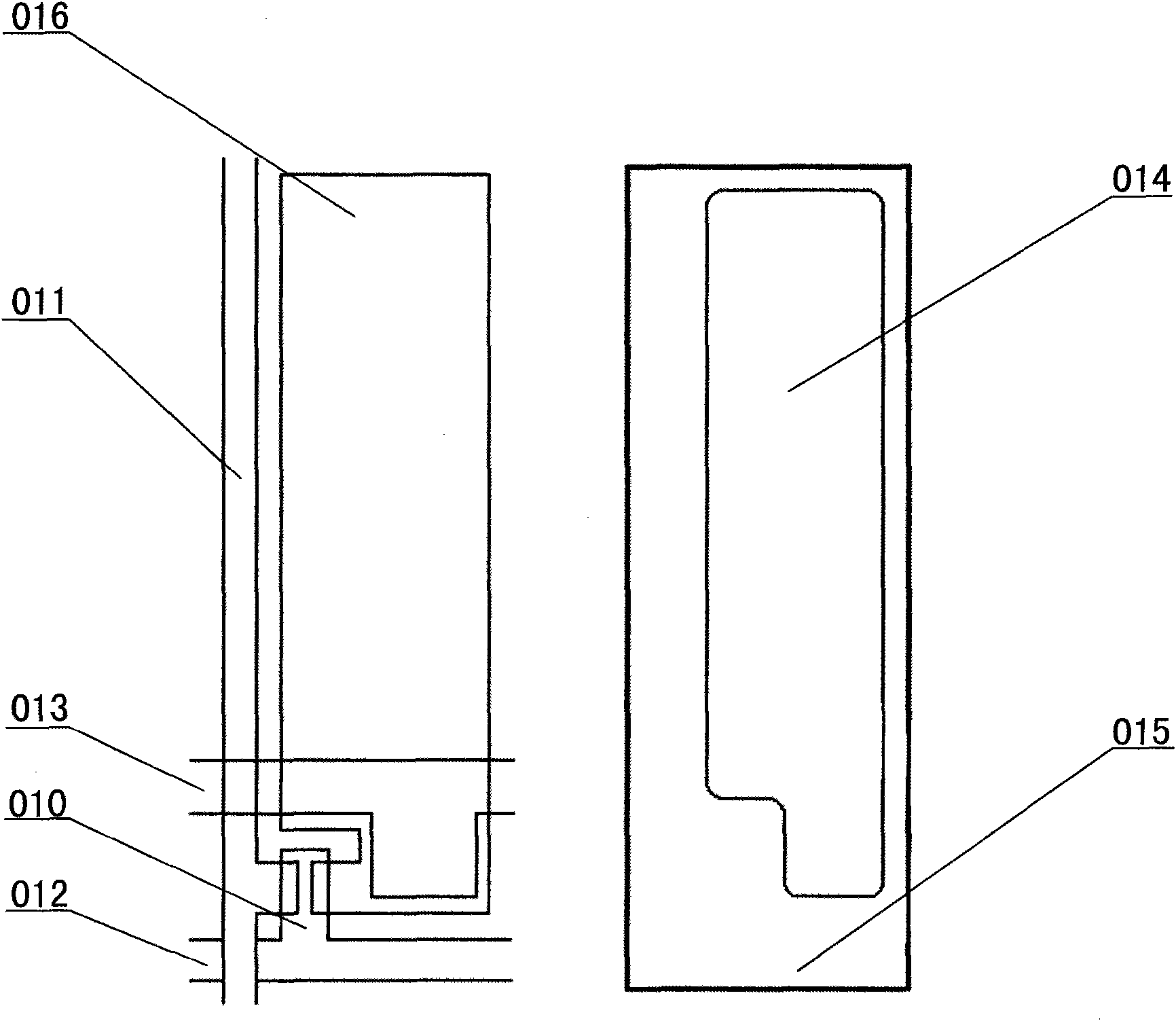
Due to the presence of uncertain electric fields on the surface of these driving components, the liquid crystal molecules above them will be arranged in an unpredictable manner, resulting in an uncontrollable bright state display, which reduces the contrast and display effect of the display; in addition, external light irradiates these driving components. , especially on TFT devices, it will also lead to abnormal performance and affect the normal display of pixels; therefore, it is generally necessary to set a layer of light-shielding layer 015 on the corresponding position of the upper substrate to cover, but this will inevitably lead to the effective reflection area ratio of the pixel ( That is, the decrease in the ratio of the reflective display area to the pixel area)
The decrease in the effective reflection area ratio will inevitably lead to a reduction in the use of external light by the entire pixel. Since the display can only work with ambient light, this will inevitably reduce the readability of the display.
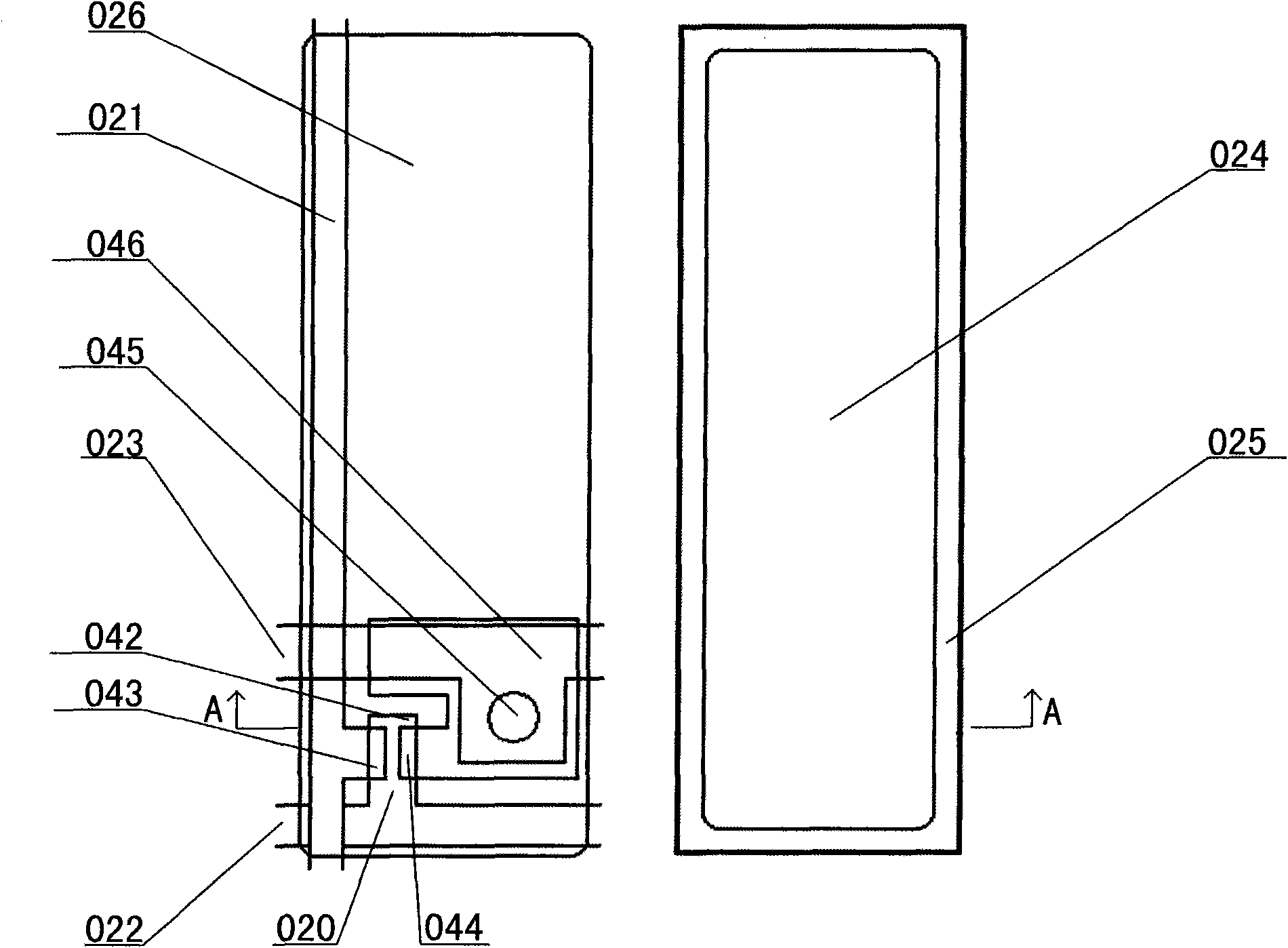
[0008] In order to solve the above problems, such as image 3 As shown, someone proposed another high-precision array-type reflective liquid crystal display. In the scheme, a multi-layer display structure and a connection method of via holes are used to realize the connection between the pixel electrode 026 (ie, the reflective area) and the driving component (ie, the TFT). devices 020, data lines 021, scanning lines 022, common capacitance lines 023 and other driving components) overlap to increase the effective reflection area ratio, but for the area between the effective display area 024 of adjacent pixels, it is still necessary to use a light-shielding layer 025 Masking, since the light-shielding layer is generally formed with a photoresist with a relatively large thickness (>1 μm), its pattern is difficult to achieve the accuracy of other film layers, and it is generally placed on the upper substrate, so a certain area needs to be reserved to prevent Due to the offset of the masked area caused by the alignment deviation of the upper and lower substrates, it is still impossible to design the width of the light-shielding layer too small, so that the effective reflection area ratio is still low and the ideal display effect cannot be achieved.

Method used


Image

  • Reflection-type TFT LCD and making method thereof
  • Reflection-type TFT LCD and making method thereof
  • Reflection-type TFT LCD and making method thereof

Examples


Embodiment Construction

[0059] Further description will be given below in conjunction with the accompanying drawings and preferred embodiments of the present invention.

[0060] The first embodiment: the upper surface of the pixel electrode is set as a reflective surface.

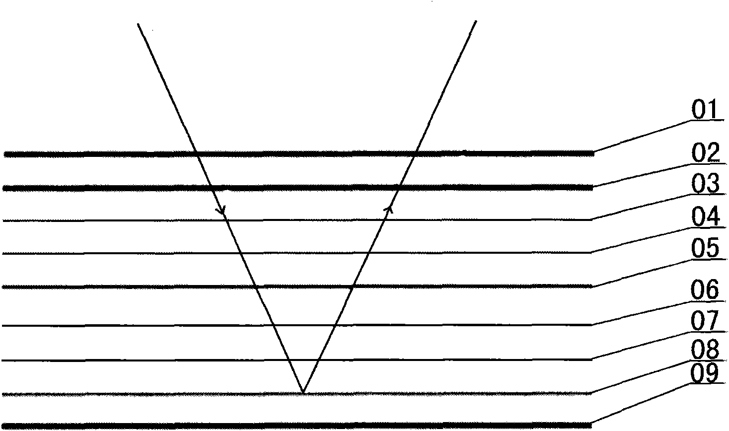
[0061] like Figure 7 As shown, the reflective TFT liquid crystal display of the first embodiment includes a lower substrate 10, a driving component layer 9, a light absorbing layer 8, a pixel electrode layer 7, a lower alignment layer 6, a liquid crystal layer 5, and an upper alignment layer arranged sequentially. The layer 4, the common electrode layer 3, the upper substrate 2, the polarizer 1, and the upper surface of the pixel electrode layer 7 constitute a reflective surface. The gap between two adjacent pixel electrodes 11 (that is, the gap between two adjacent reflective surfaces) constitutes a light absorption gap 13, and the light absorption gap 13 constitutes a black border area between two adjacent pixels because no li...


PUM


Abstract

The invention relates to a reflection-type TFT (Thin Film Transistor) LCD (liquid crystal display) and a making method thereof. A light absorption layer is arranged below a reflection surface, rays can enter the light absorption layer below the reflection surface through a light absorption gap and can be absorbed by the light absorption layer without irradiating the upper surface of a driving part to cause the failure of the driving part. Accordingly, the light absorption layer can substitute a black light-shielding layer in the prior art, and a black border region is formed between two adjacent pixels. The pixel electrodes or the reflection layer is extremely thin, and the pattern making thereof has extremely high accuracy so that the pattern of the black border region also has extremely high accuracy. Moreover, the black border region and the pixel electrodes are formed on the same substrate, the problem of pattern pasting contraposition errors among different substrates is inessential, and contraposition errors of different film layers of the same substrate are generally very small so that the black border region can be designed very narrow to acquire a larger pixel reflection display area and an effective reflection area ratio.

Description

technical field [0001] The invention relates to a liquid crystal display, in particular to a reflective TFT liquid crystal display and a manufacturing method thereof. Background technique [0002] Liquid crystal display has the characteristics of light and thin, but it does not emit light by itself, and it needs to rely on external light source or ambient light to achieve readability. For liquid crystal displays used in portable and mobile devices, the external light source often consumes much more battery power than the display itself, resulting in the need to frequently charge the battery and affect its portability. Therefore, in some applications, more emphasis is placed on portability In advanced equipment, it is imperative to use a reflective liquid crystal display that does not require an external light source. [0003] For reflective liquid crystal displays, it is generally recognized that it is designed as normal white (Normal White), which can obtain higher brightn...

Claims


Application Information

Patent Timeline
Patent Type & Authority Applications(China)
IPC IPC(8): G02F1/1335G02F1/1333
Inventor 林钢吕岳敏吴永俊沈奕余荣刘骥丁娟
Owner SHANTOU GOWORLD DISPLAY (PLANT II) CO LTD
Learn More