Linear drive, in particular a rack and pinion drive

Inactive Publication Date: 2009-12-31
WITTENSTEIN GROUP
View PDF12 Cites 4 Cited by
  • Summary
  • Abstract
  • Description
  • Claims
  • Application Information

AI Technical Summary

Benefits of technology

[0009]The object of the present invention is to provide a linear drive of the type mentioned at the beginning that eliminates the above-mentioned disadvantages and that also permits a simple, effective and inexpensive variation of the preload on the pinion in relation to the linear guide during operation and in response to changing loads and accelerations. In addition, the motor current consumption should be reduced, and wear of the pinion and linear guide and integrated drive elements should also be reduced with an increase in overall rigidity.
[0012]Corresponding guide elements are provided that as linear guides can take the form preferably of leaf spring elements, roller guides, etc. that permanently guarantee a certain preload or a variable preload during operation. The selected preload can be permanently held constant during operation in that the force acting on the pinion is permanently measured using corresponding force and / or position sensors and then adjusted via the actuators. In this way a preload force can be permanently held constant during operation. Force sensors for feed and / or preload force are preferably integrated into the unit so that the preload force can be variably influenced via the actuators during operation. This also ensures that the pinion contacts the linear guide with a permanently constant, variable preload force with the preload force being adapted or varied according to the load and / or acceleration and / or speed during operation. This allows backlash to be reliably avoided with an increased machine precision and higher machine dynamics so that a higher machine performance on, for example, machine tools with high-speed infeed such as for example laser cutting and laser punching machines can be guaranteed. Furthermore, an extremely narrow design can be guaranteed thanks to a broad adaption range that guarantees rapid installation during operation with minimum wear and low maintenance costs.
[0013]The relatively large adjustment travel permits not only the freedom from backlash with large manufacturing deviations, wear and thermal expansion to be achieved, but also considerably simplifies the installation by eliminating adjustments to the position of the motor element and the alignment and straightness of the linear guide.

Problems solved by technology

There is generally a slight backlash between pinion and linear guide, in particular a tooth face contact backlash if pinion and linear guide have flanks.
A disadvantage here is that with the conventional linear drives or rack and pinion drives with pinion and rack, machine precision and machine dynamics are significantly reduced, since for example the integrated drive rigidities vary.
In addition, the tooth flanks of pinion and rack are subject to a certain wear, which in turn also leads to backlash.
The high wear and also the lack of precision is caused in particular by the mechanically hard preload of the integrated drive, resulting in very large integrated drives having to be employed.
Furthermore, a preload force on the pinion is by no means constant, as for example with different loads and speeds, but also accelerations and imprecisions in the linear guide can result in differing wear or exists from the outset due to manufacturing inaccuracies.
In addition, inaccuracies in the linear guide caused by, for example, thermal expansion are not compensated, so that different wear is caused to the linear guide and the pinion.
This cannot be guaranteed with the conventional linear drives.

Method used


Image

  • Linear drive, in particular a rack and pinion drive
  • Linear drive, in particular a rack and pinion drive
  • Linear drive, in particular a rack and pinion drive

Examples


Embodiment Construction

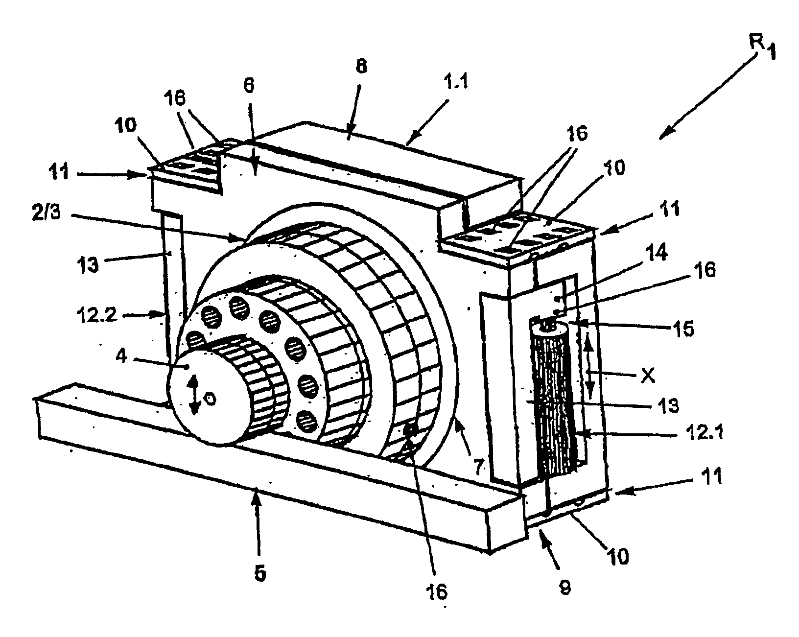
[0018]According to FIG. 1, a linear drive R1 according to the invention exhibits a retaining element 1.1 that has the form roughly of a plate and serves as a mounting for a motor element 2 possibly with a downline or integrated drive 3 on which a pinion 4 is mounted. The pinion 4 interacts with or meshes with a linear guide 5. The pinion 4 can, for example, be designed as a gear wheel and meshes with corresponding tooth faces of the linear guide 5.

[0019]The present invention should, however, also cover the case in which, for example, the linear drive R1 can move or travel in relation to the linear guide 5 in that the pinion is driven, or that the linear drive R1 is mounted in or on a machine frame or other subframe and drives the linear guide 5. Racks, straight guides, curved tracks or even circular tracks can be provided as the linear guide 5. The invention is not limited to these aspects. It should also be considered that, for example, the pinion 4 interacts with the linear guide ...


PUM


Abstract

The invention relates to a linear drive, in particular a rack and pinion drive, comprising at least one motor element (2) which is mounted on or in a retaining element (1.1, 1.2). The motor element (2) drives, directly or indirectly, a pinion (4), optionally, via an integrated drive (3), said pinion co-operating with a linear guide (5). According to the invention, the retaining element (1.1, 1.2) can be displaced by at least one actuator (12.1 to 12.3) in relation to a receiving element (6).

Description

BACKGROUND[0001](1) Field of the Invention[0002]The present invention relates to a linear drive, in particular to a rack and pinion drive, with at least one motor element mounted on or in a retaining element, the motor element driving a pinion directly or indirectly, optionally via an integrated drive, said pinion interacting with a linear guide and to a process for operating the linear drive.[0003](2) Prior Art[0004]The conventional linear drives or conventional rack and pinion drives are known and common on the market in a wide range of forms and embodiments. In these, a pinion that interacts with a linear guide is driven via a common powertrain using motor element and possibly integrated or downline drive in order to compensate backlash in a gearing. There is generally a slight backlash between pinion and linear guide, in particular a tooth face contact backlash if pinion and linear guide have flanks.[0005]A disadvantage here is that with the conventional linear drives or rack an...

Claims


Application Information

Patent Timeline
IPC IPC(8): F16H55/28B23Q5/02B23Q5/38B23Q5/56
CPCB23Q5/385B23Q5/56Y10T74/19623F16H2057/123F16H55/28
Inventor BAYER, THOMASMICHEL, FRANK
Owner WITTENSTEIN GROUP
Why Eureka
Try Eureka