Finite element modeling method for predicting forging force in rotary swaging process

A modeling method and finite element technology, applied in special data processing applications, instruments, electrical digital data processing, etc., can solve problems such as heavy workload and long time consumption

Inactive Publication Date: 2010-09-22
BEIJING UNIV OF TECH
View PDF2 Cites 6 Cited by
  • Summary
  • Abstract
  • Description
  • Claims
  • Application Information

AI Technical Summary

Problems solved by technology

[0004] The present invention aims at the problem of large workload and long time consumption when drawing the complex movement trajectory of the object in the commercial finite element software, and calculates the radial and axial movement trajectory of the swaging die relative to the workpiece to be swaged by using the general mathematical calculation software The figure is output as a finite element input format file, and the finite element model of swaging is established by using the general finite eleme

Method used


Image

  • Finite element modeling method for predicting forging force in rotary swaging process
  • Finite element modeling method for predicting forging force in rotary swaging process
  • Finite element modeling method for predicting forging force in rotary swaging process

Examples


Embodiment Construction

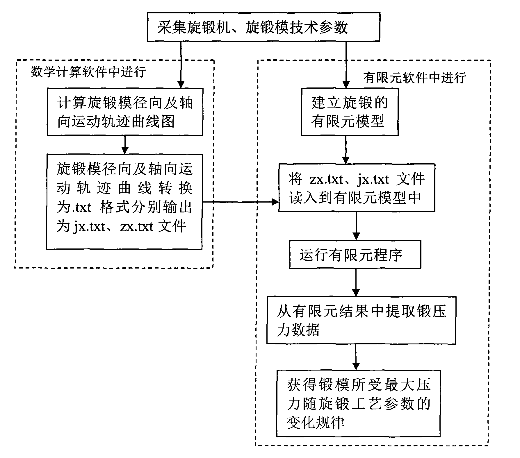
[0044] Flow chart of the present invention sees figure 1 . Below in conjunction with accompanying drawing, take the prediction of the forging pressure of pure magnesium swaging process as example, specifically illustrate the method of the present invention, but protection scope of the present invention is not limited to following embodiment:

[0045] Step 1: Collect the original technical parameters of swaging, including: spindle speed of swaging machine, feeding speed, number of rollers in the machine head, diameter of incoming material, diameter after swaging, length of compression zone, length of sizing belt, cone The feed angle and initial swaging temperature are shown in Table 1.

[0046] Table 1 Calculate the original technical parameters required for swaging forging pressure

[0047]

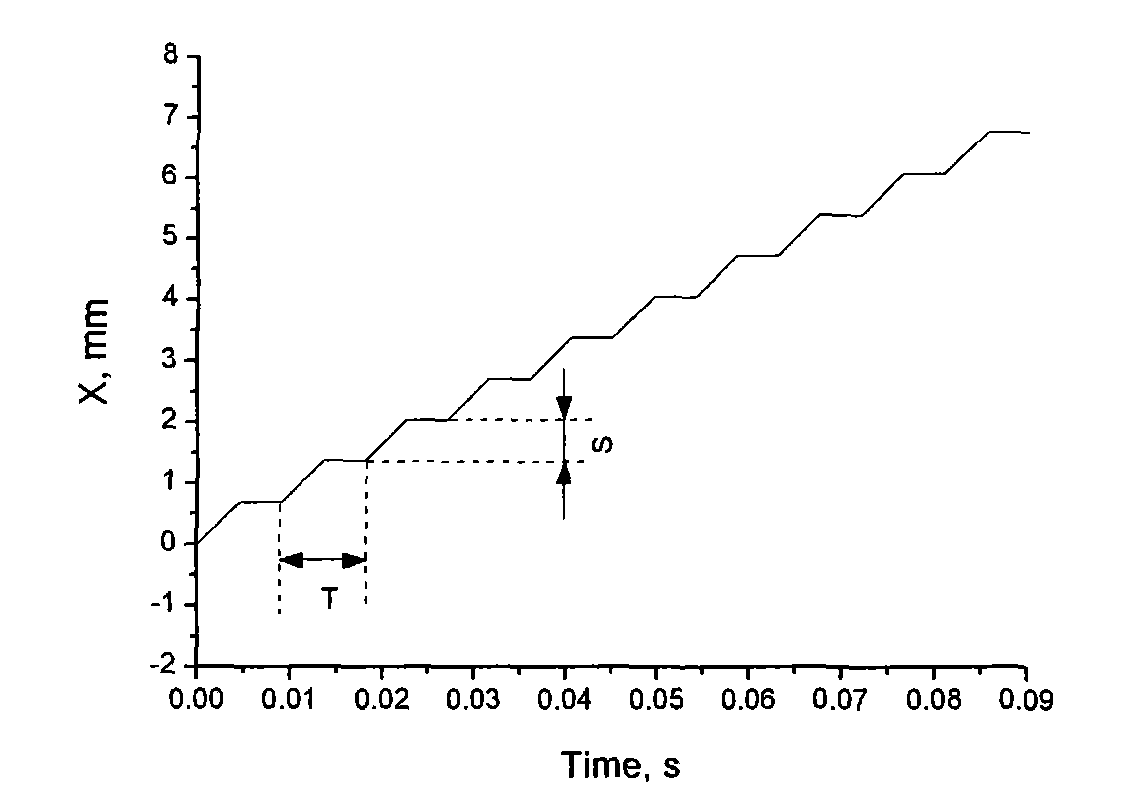
[0048] Step 2: Use the mathematical software matlab to calculate the curves of the radial and axial movement trajectories of the swaging die relative to the workpiece to be swaged, a...


PUM


Abstract

The invention discloses a finite element modeling method for predicting forging force in the rotary swaging process and belongs to the technical field of plastic forming. The forging force is calculated by an empirical formula in the conventional rotary swaging industry, the calculation accuracy is low, and the change rule of the forging force along the rotary swaging technological parameters cannot be predicted. Due to complex motion track of the rotary swaging molds, a report for calculating the rotary swaging forging force by the finite element method is absent up to now. The finite element modeling method comprises the following steps of: calculating a motion track diagram of the rotary swaging mold relative to workpieces subjected to the rotary swaging by using mathematical software; establishing a finite element model of the rotary swaging by using universal finite software; and combining the motion track diagram of the rotary swaging mold which is obtained by the mathematical software to realize the simulation of the forging die motion process in the finite element simulation process. The finite element modeling method can solve the problems of high workload and high time consumption when commercial finite element software draws a complex motion track of an object, can precisely calculate the change rule of the forging force along the rotary swaging technological parameters to obtain the range of the reasonable rotary swaging technological parameters, and provides a basis for accurately designing the rotary swaging molds and rotary swaging technological parameters and selecting the models of rotary swaging machines.

Description

technical field [0001] The invention belongs to the technical field of plastic forming, in particular to a finite element analysis method for predicting the forging pressure in the swaging process. Background technique [0002] Rotary forging is an advanced plastic forming process, which is widely used in various materials, such as metal (copper alloy, steel, tungsten, molybdenum, niobium, etc.), metal matrix composites, metal oxides and other wire rod forming processes. Its advantages are high production efficiency, high product precision, good quality, and saving metal materials. [0003] Rotary forging belongs to multi-head spiral stretching, which has the characteristics of pulse forging and multi-directional forging. The accurate calculation of the swaging pressure plays an important role in the selection of the swaging machine model, the design of the swaging die and the design of the swaging process parameters. Due to the complexity of the movement process of the sw...

Claims


Application Information

Patent Timeline
IPC IPC(8): G06F17/50
Inventor 荣莉聂祚仁
Owner BEIJING UNIV OF TECH
Why Eureka
Try Eureka