
Optical fiber extrinsic Fabry-Perot interference ultrasonic sensing and detection device

A detection device, ultrasonic sensing technology, applied in the direction of measuring device, measuring ultrasonic/sonic/infrasonic, testing dielectric strength, etc., to achieve the effect of easy packaging, convenient mass production, and improved stability

Inactive Publication Date: 2010-06-30
SHANGHAI UNIV
View PDF0 Cites 50 Cited by
  • Summary
  • Abstract
  • Description
  • Claims
  • Application Information

AI Technical Summary

Problems solved by technology

[0005] The traditional ultrasonic detection method is to use piezoelectric transducers to detect ultrasonic waves. This method converts ultrasonic signals into electrical signals and is also susceptible to electromagnetic interference.

Method used


Image

  • Optical fiber extrinsic Fabry-Perot interference ultrasonic sensing and detection device
  • Optical fiber extrinsic Fabry-Perot interference ultrasonic sensing and detection device
  • Optical fiber extrinsic Fabry-Perot interference ultrasonic sensing and detection device

Examples


Embodiment 1

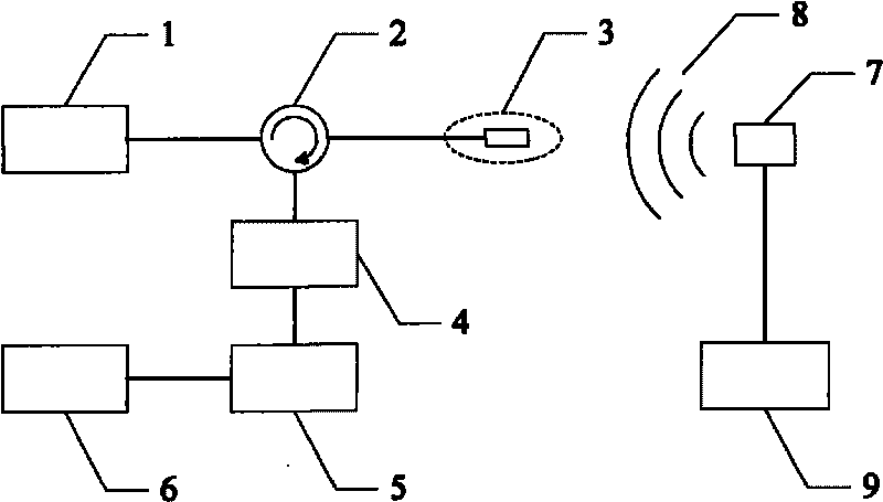
[0021] Embodiment one: see figure 1 , the optical fiber Fabry-Perot ultrasonic sensing device includes: a light source 1, the light source 1 is connected to an optical fiber circulator 2, and an interface of the optical fiber circulator 2 is connected to an optical fiber Fabry-Perot ultrasonic Sensor 3, another interface connects an oscilloscope 6 through a photoelectric conversion module 4 and a signal amplification module 5, and a signal generator 9 connects a piezoelectric transducer 7, and this piezoelectric transducer produces ultrasonic signal 8, transmits to The Fabry-Perot ultrasonic sensor 3; the light source 1 shown is a 1550nm light source, and the fiber optic circulator 2 is a 1550nm fiber optic circulator.

Embodiment 2

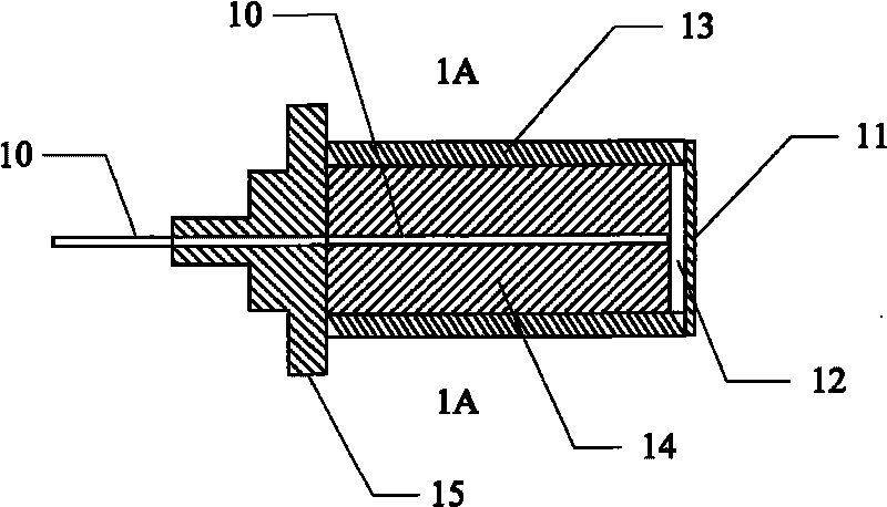
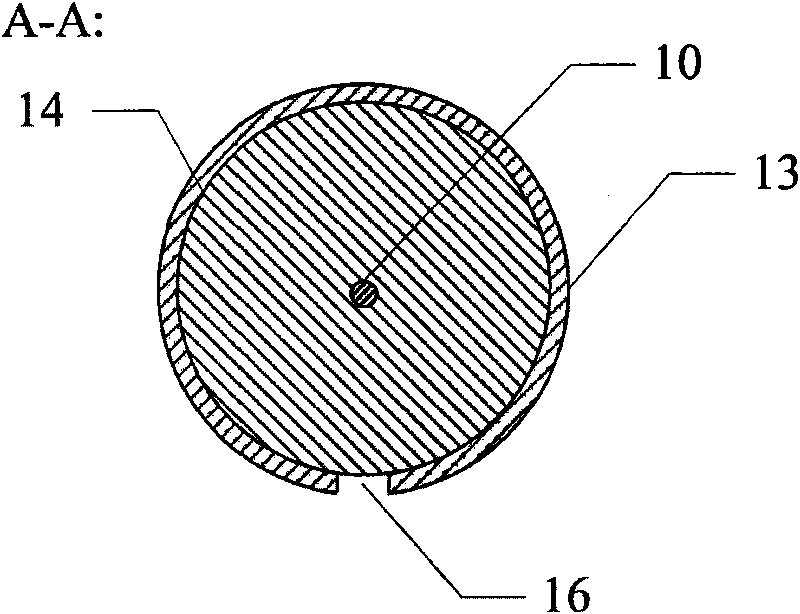
[0022] Embodiment two: see figure 2 , the above-mentioned present embodiment is the same as Embodiment 1, and the special features are as follows: the basic structure of the optical fiber Fabry-Perot ultrasonic sensor is: a single-mode optical fiber 10 is inserted in an inner ceramic sleeve 14 and then an outer jacket The ceramic sleeve 13 has a metal base 15 and a quartz vibrating membrane 11 at the two ends of the inner ceramic sleeve 14 and the outer ceramic sleeve 13 respectively. The inner end surface of the single-mode optical fiber 10, the inner surface of the quartz vibrating membrane 11, the inner wall surface of the outer ceramic sleeve 13 and the end surface of the inner ceramic sleeve 14 form a Fabry-Perot cavity 12; the Fabry-Perot The cavity length of the cavity is the distance from the end face of the single-mode optical fiber 10 to the inner surface of the quartz vibrating membrane 11; the inner diameter of the outer ceramic sleeve 13 of the optical fiber Fabr...


PUM


Abstract

The invention discloses an optical fiber extrinsic Fabry-Perot interference ultrasonic sensing and detection device, comprising a 1550nm light source, a 1550nm optical circulator, an optical fiber Fabry-Perot ultrasonic sensor, a photoelectric transition module, a signal amplification module, an oscillograph, a piezoelectric transducer and a signal generator. The basic structure of the optical fiber Fabry-Perot ultrasonic sensor is composed of a single mode optical fiber, a quartz vibrating membrane, an outer ceramic bushing, an inner ceramic bushing and a metal base. The light emitted by the 1550nm light source reaches the optical fiber Fabry-Perot ultrasonic sensor through the optical circulator, when ultrasonic wave acts on the ultrasonic sensor, as the light reflected by the optical fiber Fabry-Perot ultrasonic sensor is modulated by the ultrasonic signal, the reflected light reaches the photoelectric conversion module by the circulator and then is converted into an electric signal, and the ultrasonic signal can be observed by the oscillograph after amplification. The invention has simple structure, easy manufacture, low cost and high sensitivity, strong practicability, easy encapsulation and is convenient for mass production, and can be applied to related fields of industrial detection, power system safety and the like.

Description

technical field [0001] The invention uses the optical fiber extrinsic Fabry-Perot interference ultrasonic sensing device to detect the acoustic emission source, especially for detecting ultrasonic signals generated by acoustic emission sources such as material damage and transformer partial discharge, and belongs to the optical fiber sensing field, Background technique [0002] Acoustic emission sources in the usual sense generally refer to various deformation and fracture mechanisms produced by materials under the action of external forces. When this mechanism occurs, it will be accompanied by the generation of stress waves and spread to the surroundings. Acoustic emission is an important non-destructive testing and evaluation method. It uses highly sensitive sensors to accept the damage from these materials or components when they are subjected to external forces and long before they are damaged. Acoustic emission signals, through the analysis and processing of these sign...

Claims


Application Information

Patent Timeline
IPC IPC(8): G01H9/00G01R31/12
Inventor 陈娜陈振宜孙庆国丁悦通张超王廷云庞拂飞
Owner SHANGHAI UNIV
Learn More