Process for forming a ferroelectric film, ferroelectric film, ferroelectric device, and liquid discharge apparatus
A ferroelectric and film-forming technology, which is applied in the field of liquid discharge devices to form ferroelectric films, can solve the problems of Pb, ferroelectricity deterioration, technical impracticality, etc., and achieve the suppression of ferroelectricity reduction, ferroelectricity performance improvement and good ferroelectricity
- Summary
- Abstract
- Description
- Claims
- Application Information
AI Technical Summary
Problems solved by technology
Method used
Image


Examples
Embodiment 1
[0177] As a substrate for film formation, an electrode-mounted substrate in which a 30-nm-thick Ti close-contact layer and a 300-nm-thick Ir lower electrode were superimposed in this order on a 25-mm-square Si substrate was prepared.
[0178] For the electrode-mounted substrate prepared in this way, by using the RF sputtering device at a vacuum of 0.5 Pa and in Ar / O 2 Mixed atmosphere (O 2 Film formation was performed under the conditions in (volume fraction: 2.5%). The target composition was set to various compositions, thereby forming each of a plurality of Bi-doped PZT ferroelectric films having different Bi doping concentrations. In each target composition, the Zr:Ti molar ratio was set to Zr:Ti=52:48.
[0179] The substrate-target separation distance was set at 60 mm. The film formation temperature Ts was set at 525°C. At 2.5W / cm 2 Film formation is performed with RF electric power applied to the target. The film thickness of the ferroelectric film was set to 4 μm. ...
Embodiment 2
[0207] The film formation of the real PZT film and the Nb-PZT film was performed in the same manner as in Example 1, except that the specific film formation conditions were changed. For each of the true PZT film and the Nb-PZT film formed, a ferroelectric device was obtained. For the film formation of real PZT films, use the composition consisting of Pb 1.3 Zr 0.52 Ti 0.48 o 3 represents the target. For the film formation of Nb-PZT film, use the composition consisting of Pb 1.3 Zr 0.43 Ti 0.44 Nb 0.13 o 3 represents the target.
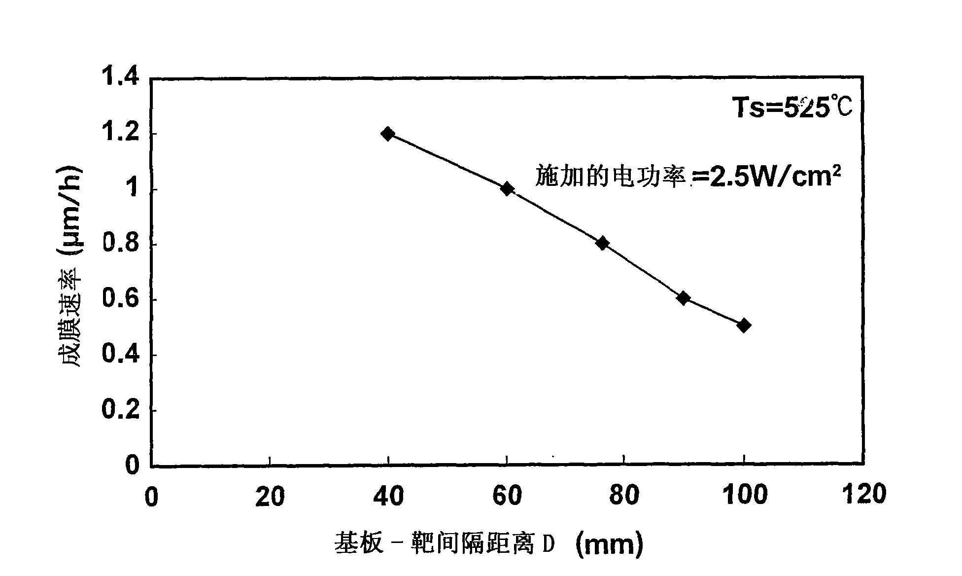
[0208] The film formation temperature Ts was set at 525°C. 2.5W / cm 2 The RF electrical power is applied to the target. Film formation was performed under the conditions of the substrate-target spacing distance D of D (mm) = 40 mm, 60 mm, 75 mm, 100 mm and 120 mm. The Nb-PZT film was formed under the condition of the substrate-target separation distance D of D (mm) = 60 mm, while the PZT film was formed under the condition of other values ...
Embodiment 3
[0215] The film formation temperature Ts was set to Ts=420° C., the substrate-target separation distance D was set to D (mm)=60 mm, and other conditions were set to be the same as in Example 2. In this way a PZT film is formed.
[0216] Under the above conditions, perovskite crystals with (100) orientation and good crystal orientation properties were obtained. (Perovskite crystals contain a small amount of pyrochlore phase).
[0217] (Summary of the results of Examples 2 and 3)
[0218] Figure 14 is a graph showing the results of XRD measurements performed on all samples of Examples 2 and 3 and other samples formed under different conditions, in which the film formation temperature Ts is plotted on the horizontal axis, and in which the substrate-target separation distance D plotted on the vertical axis.
[0219] Figure 14 Note that, for the PZT film or the Nb-PZT film, after adjusting the film-forming conditions within such a range as to satisfy the formulas (1) and (2)...
PUM
| Property | Measurement | Unit |
|---|---|---|
| Thickness | aaaaa | aaaaa |
| Thickness | aaaaa | aaaaa |
| Piezoelectric constant | aaaaa | aaaaa |
Abstract
Description
Claims
Application Information
 - R&D
- Intellectual Property
- Life Sciences
- Materials
- Tech Scout
- Unparalleled Data Quality
- Higher Quality Content
- 60% Fewer Hallucinations
Browse by: Latest US Patents, China's latest patents, Technical Efficacy Thesaurus, Application Domain, Technology Topic, Popular Technical Reports.
© 2025 PatSnap. All rights reserved.Legal|Privacy policy|Modern Slavery Act Transparency Statement|Sitemap|About US| Contact US: help@patsnap.com