
Bridge type surface acoustic wave transducer in micro-optical-electro-mechanical gyroscope

A micro-opto-electromechanical, surface acoustic wave technology, applied in the direction of electrical components, impedance networks, etc., can solve the problems of large absorption loss, large device size, reduced output optical power and acousto-optic coupling efficiency, etc., to reduce absorption, reduce metal The effect of lengthening

Inactive Publication Date: 2012-03-14
INST OF ACOUSTICS CHINESE ACAD OF SCI +1
View PDF5 Cites 0 Cited by
  • Summary
  • Abstract
  • Description
  • Claims
  • Application Information

AI Technical Summary

Problems solved by technology

In the waveguide collinear acousto-optic device, the light wave propagating in the waveguide passes through the area covered by the metal electrode, and the metal will absorb part of the light energy to generate the transmission loss of light intensity. The loss is proportional to the length of the metal covered area on the optical path. Now Some conventional interdigital transducers have large absorption loss due to the long metallization length on the optical path, which reduces the output optical power and acousto-optic coupling efficiency
Although the quasi-collinear acousto-optic device avoids the absorption of light energy by metal electrodes, it also has its own disadvantages, such as relatively large device size, and the inability to fully utilize the acoustic power.

Method used


Image

  • Bridge type surface acoustic wave transducer in micro-optical-electro-mechanical gyroscope
  • Bridge type surface acoustic wave transducer in micro-optical-electro-mechanical gyroscope

Examples


Embodiment Construction

[0020] The bridge-type surface acoustic wave transducer in the micro-opto-electromechanical gyroscope of the present invention will be described in detail below with reference to the accompanying drawings and specific embodiments.

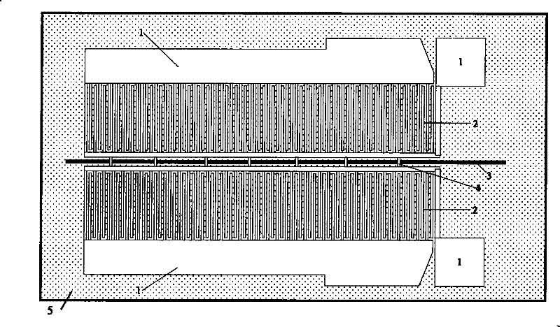
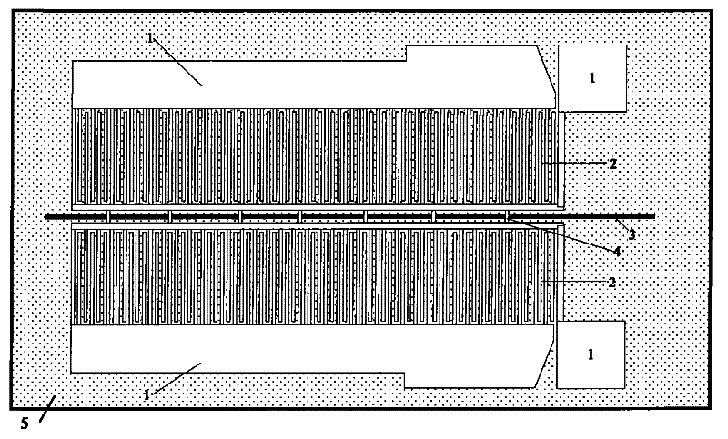
[0021] figure 1 It is a schematic diagram of the overall structure of the bridge-type surface acoustic wave transducer in the micro-opto-electromechanical gyroscope of the present invention. Such as figure 1 As shown, the surface acoustic wave transducer of the present invention is a surface acoustic wave transducer with a grouped bridging electrode structure in a micro-opto-electromechanical gyro device based on an acousto-optic waveguide structure. On the base material 5, photolithography, The embedded strip-shaped acousto-optic waveguide area 3 is made by coating, diffusion or etching processes. In addition, on the base material 5, there are also: pressure welding electrodes 1, interdigital electrodes 2 and bridges spanning the upper part of th...


PUM


Abstract

The invention relates to a bridge type surface acoustic wave transducer in a micro-optical-electro-mechanical gyroscope. An embedded strip-shaped acoustic-optical waveguide region is produced on a substrate material, the bridge type surface acoustic wave transducer is further provided with a pressure welding electrode, interdigital electrodes and a bridging electrode, electrode structures of the interdigital electrodes are divided into two groups and respectively positioned on the upper side and the lower side of the acoustic-optical waveguide region with the interval of less than six sound wave wavelengths, and the two groups of the interdigital electrodes are connected through the bridging electrode and penetrate the acoustic-optical waveguide region. When a driving power supply is imposed between the upper group and the lower group of the surface acoustic wave interdigital electrodes for generating surface acoustic waves, an acoustic wave field of the acoustic-optical waveguide region and the region of the interdigital electrodes are completely uniform and consistent, thereby leading acoustic waveguide of the acoustic-optical waveguide region to have no sound field mutation. The bridge type surface acoustic wave transducer adopts the bridging form for reducing the area of a metal electrode of acoustic-optical waveguide under the premise of keeping the acoustic wave field ofan acoustic-optical active region unchanged, thereby not only keeping the characters of the acoustic wave field, but also effectively reducing the absorption of optical waves of the metal electrode.

Description

technical field [0001] The invention relates to a surface acoustic wave generating and receiving device in a micro-opto-electromechanical gyro device based on an acousto-optic waveguide structure, in particular to a surface acoustic wave transducer in a micro-opto-electromechanical gyro with a bridge structure. Background technique [0002] Acousto-optic technology has been developed since the advent of lasers in the early 1960s. It has been developed for nearly 40 years. Laser beam deflection and modulation has been widely used, and it also shows very significant advantages in signal processing, optical computing, optical communication and other fields. [0003] Acousto-optic devices can be classified into two categories: bulk and waveguide. Bulk acousto-optic devices are developed using the bulk-wave acousto-optic effect. Its research started early and has become mature. It has been applied in many fields, but the limitations of volume, driving power and bandwidth limit r...

Claims


Application Information

Patent Timeline
Patent Type & Authority Patents(China)
IPC IPC(8): H03H9/145
Inventor 李红浪何世堂孟彦彬陈淑芬赵毅
Owner INST OF ACOUSTICS CHINESE ACAD OF SCI
Learn More