Preheating system of plate heat exchanger of hot blast furnace

A technology of plate heat exchanger and hot blast stove, which is applied in the direction of indirect heat exchanger, heat exchanger type, lighting and heating equipment, etc., which can solve the problems of reduced heat transfer efficiency, limited pressure resistance, and high consumption of metal materials , to achieve the effect of convenient maintenance and cleaning, high and high temperature tolerance, and less metal consumption

Active Publication Date: 2010-01-27
上海雷林工业设备有限公司
View PDF0 Cites 10 Cited by
  • Summary
  • Abstract
  • Description
  • Claims
  • Application Information

AI Technical Summary

Problems solved by technology

A shortcoming in the existing system is that the heat exchangers adopted are not ideal, and the shortcoming of the heat pipe heat exchanger is: one is that the heat exchange gas generally adopts water-steel heat pipes, and the water-steel heat pipes have limited pressure resistance. The heat temperature can easily lead to heat pipe leakage or even heat pipe bursting. The second is that the water-steel heat pipe will produce non-condensable gas during operation, and the efficiency will decrease after forming an air lock. The third is that there is a large amount of dust in the environment, and dust adhesion increases the thermal resistance of dirt. Reduce efficiency
The disadvantages of the tube heat exchanger are that the heat exchange area per unit volume of the heat exchanger is small, consume more metal materials, the heat exchange efficiency is low, and the tube heat exchanger occupies a large area.
The disadvantage of the thermal coal heat exchanger is that the heat is transferred through the heat medium, which increases the intermediate link and reduces the heat transfer efficiency.
Secondly, heat medium needs to be transported by pump, which increases power consumption
In addition, the heat medium is easy to leak, causing the heat exchanger to fail and pollute the environment
Another fundamental problem is that the hot blast stove only burns blast furnace gas, and the exhaust gas temperature of the hot blast stove is not ideal, so a higher hot blast temperature cannot be obtained

Method used


Image

  • Preheating system of plate heat exchanger of hot blast furnace
  • Preheating system of plate heat exchanger of hot blast furnace
  • Preheating system of plate heat exchanger of hot blast furnace

Examples


Embodiment Construction

[0015] The specific implementation will be described in detail below in conjunction with the accompanying drawings:

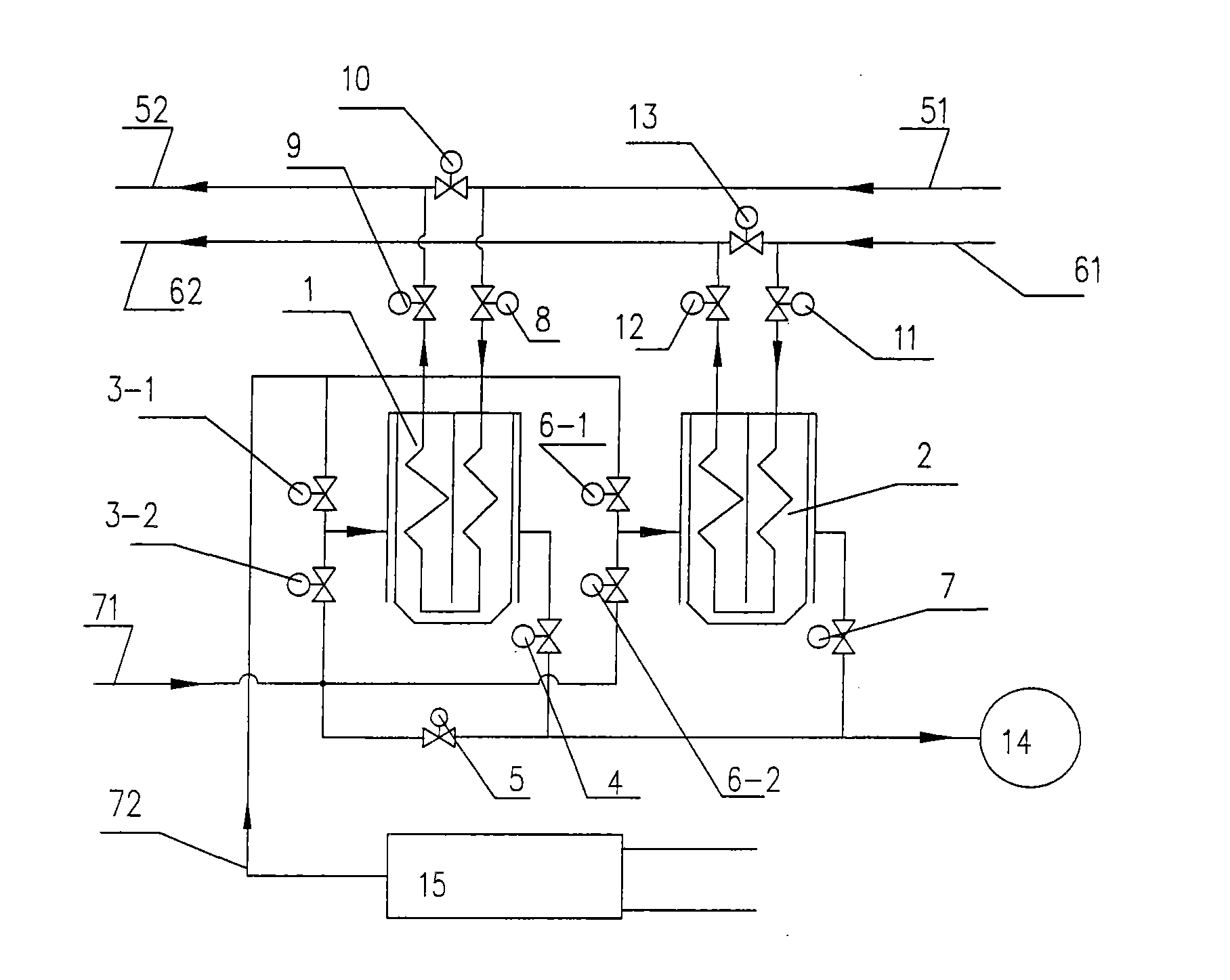
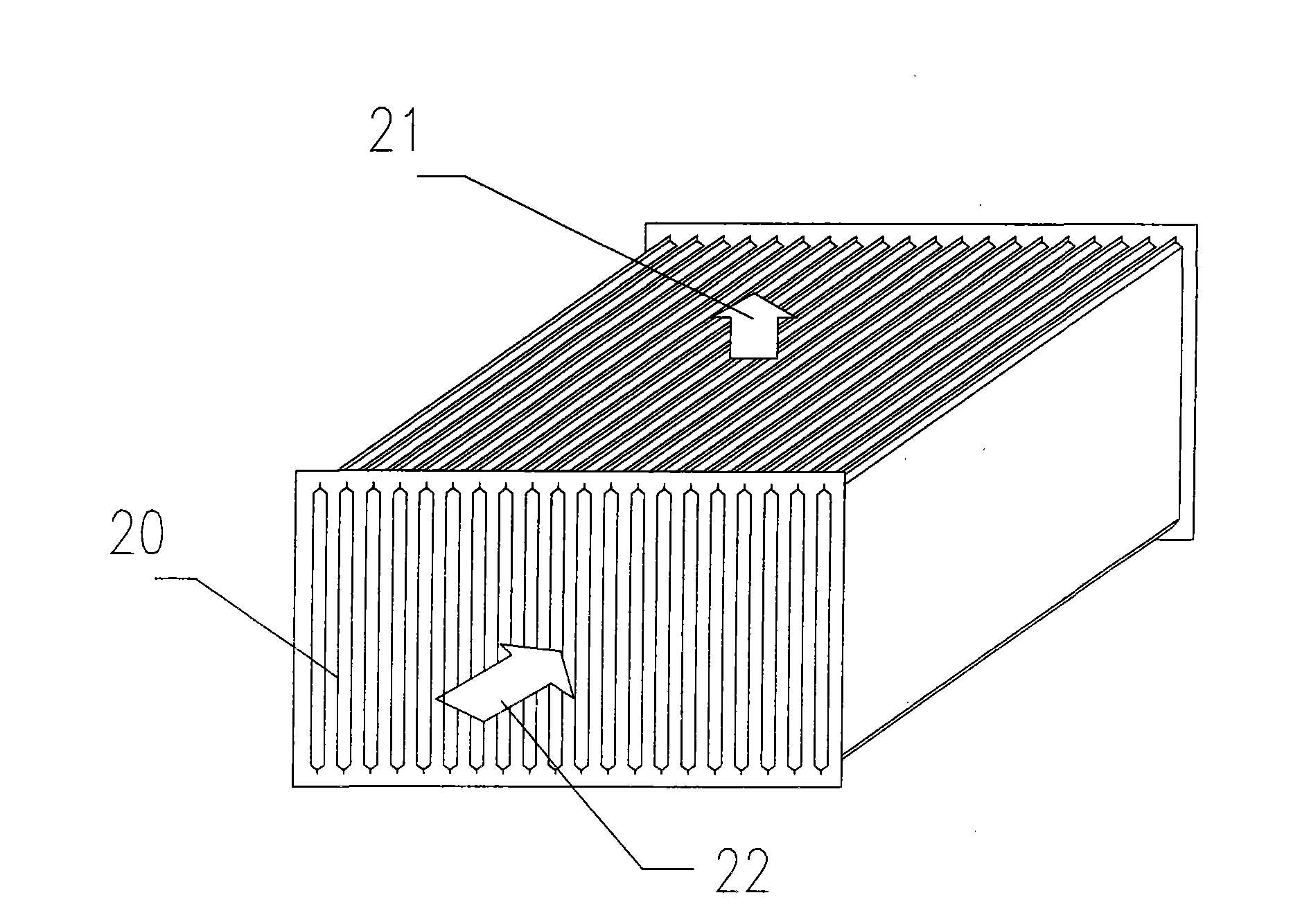
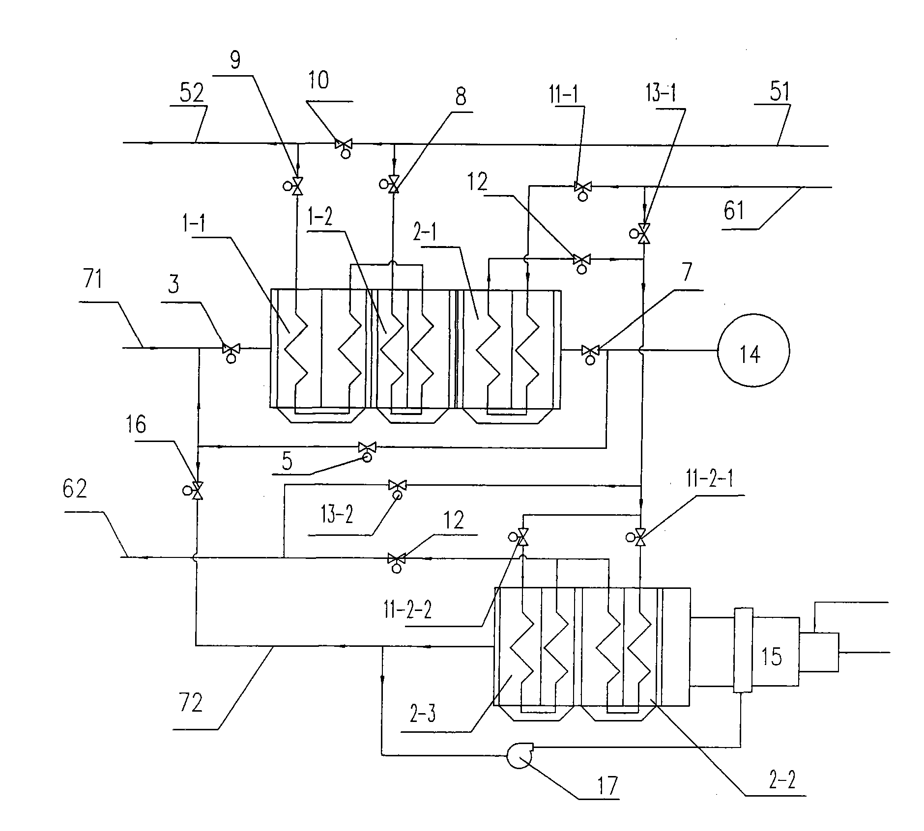
[0016] First, the legend is explained as follows: 1. Gas heat exchanger 2, air heat exchanger 3, gas heat exchanger flue gas inlet valve 4, gas heat exchanger flue gas outlet valve 5, flue gas bypass valve 6, air exchanger Heater flue gas inlet valve 7, air heat exchanger flue gas outlet valve 8, gas inlet valve 9, gas outlet valve 10, gas bypass valve 11, air inlet valve 12, air outlet valve 13, air bypass valve 14, Chimney 15, additional combustion furnace 16, additional combustion furnace flue gas valve 17, exhaust gas induced draft fan 18, hot blast stove exhaust gas outlet pipe 20, plate bundle module 21, high-heat flue gas 22, low-temperature gas or air 51, gas input pipe 52, output Pipe 61, air input pipe 62, air output pipe 71, hot blast stove exhaust gas flue 72, additional combustion furnace output pipe

[0017] figure 1 A schematic diagram of the s...


PUM


Abstract

The invention relates to a preheating system of a plate heat exchanger of a hot blast furnace, which comprises a gas input pipeline, a gas output pipeline, an air input pipeline, an air output pipeline, a hot blast furnace waste gas flue, a chimney, a plurality of heat exchangers, an additional burning furnace, a connecting pipeline and a plurality of valves. The heat exchangers are plate heat exchangers which consist of a plurality of sets of plate bundle modules, the plate bundle modules are formed by laminating convex-concave corrugated partition boards, and pyrogenic fume and low-temperature gas or air reversely flow in a crossed and alternated plate cavity to form respective inlet and outlet. The preheating system ensures the pyrogenic fume and the low-temperature gas or the air directly exchange heat through the plate wall of the partition board without an intermediate heat transfer working substance, the preheating temperature is not limited by the critical temperature and/or critical pressure of the heat transfer working substance, and a metallic material or a ceramic material has high capability of high temperature resistance, so the preheating system of the plate heat exchanger of the hot blast furnace has the advantages of adapting to higher preheating temperature and more complicated preheating process flow, and the like. The preheating system can utilize the plurality of the heat exchangers to perform different combinations to form various preheating systems, meet different preheating requirements and ensure that the preheating system has practicability.

Description

Technical field: [0001] The invention relates to the blast furnace ironmaking technology in the metallurgical industry, in particular to a hot blast stove plate heat exchanger preheating system for improving the waste heat recovery efficiency of the hot blast stove waste gas. Background technique: [0002] An effective way to save energy and reduce consumption in the blast furnace ironmaking process is to increase the blast furnace inlet air temperature. Every time the blast furnace air temperature increases by 100°C, the ton iron-coke ratio can be reduced by 20kg, the output can be increased by 4%, and the amount of coal injection can be increased by 50kg. . Therefore, all enterprises attach great importance to keeping the wind temperature at a high level for smelting operations. In the prior art, the commonly used method is the hot blast stove. The hot blast stove is a device that provides hot air to the blast furnace. Its working principle is to generate high-temperature...

Claims


Application Information

Patent Timeline
Patent Type & Authority Applications(China)
IPC IPC(8): F28D9/00
Inventor 洪晓波
Owner 上海雷林工业设备有限公司
Why Eureka
Try Eureka