
Hall gear position sensor

A gear sensor, Hall chip technology, applied in the direction of instruments, transmission control, measuring devices, etc., can solve the problem of long response time, achieve the effect of fast response time, compact structure, and reduce errors

Inactive Publication Date: 2009-09-02
NANJING AOLIAN AE&EA
View PDF0 Cites 4 Cited by
  • Summary
  • Abstract
  • Description
  • Claims
  • Application Information

AI Technical Summary

Problems solved by technology

The shifting process is a very frequent action, which requires the life of the gear selection sensor to be very high. Therefore, the non-contact method is the first choice, and the existing non-contact gear sensor is realized by linear Hall Yes, in the process of shifting, the linear Hall moves relative to the magnet. By collecting the stroke of the gear and converting it, the selected gear can be converted. Since the detection of the gear is realized by displacement detection and processing Yes, there is a large error in this way, and the response time is relatively long

Method used


Image

  • Hall gear position sensor
  • Hall gear position sensor
  • Hall gear position sensor

Examples


Embodiment Construction

[0013] The specific embodiments of the present invention will be further described below in conjunction with the accompanying drawings.

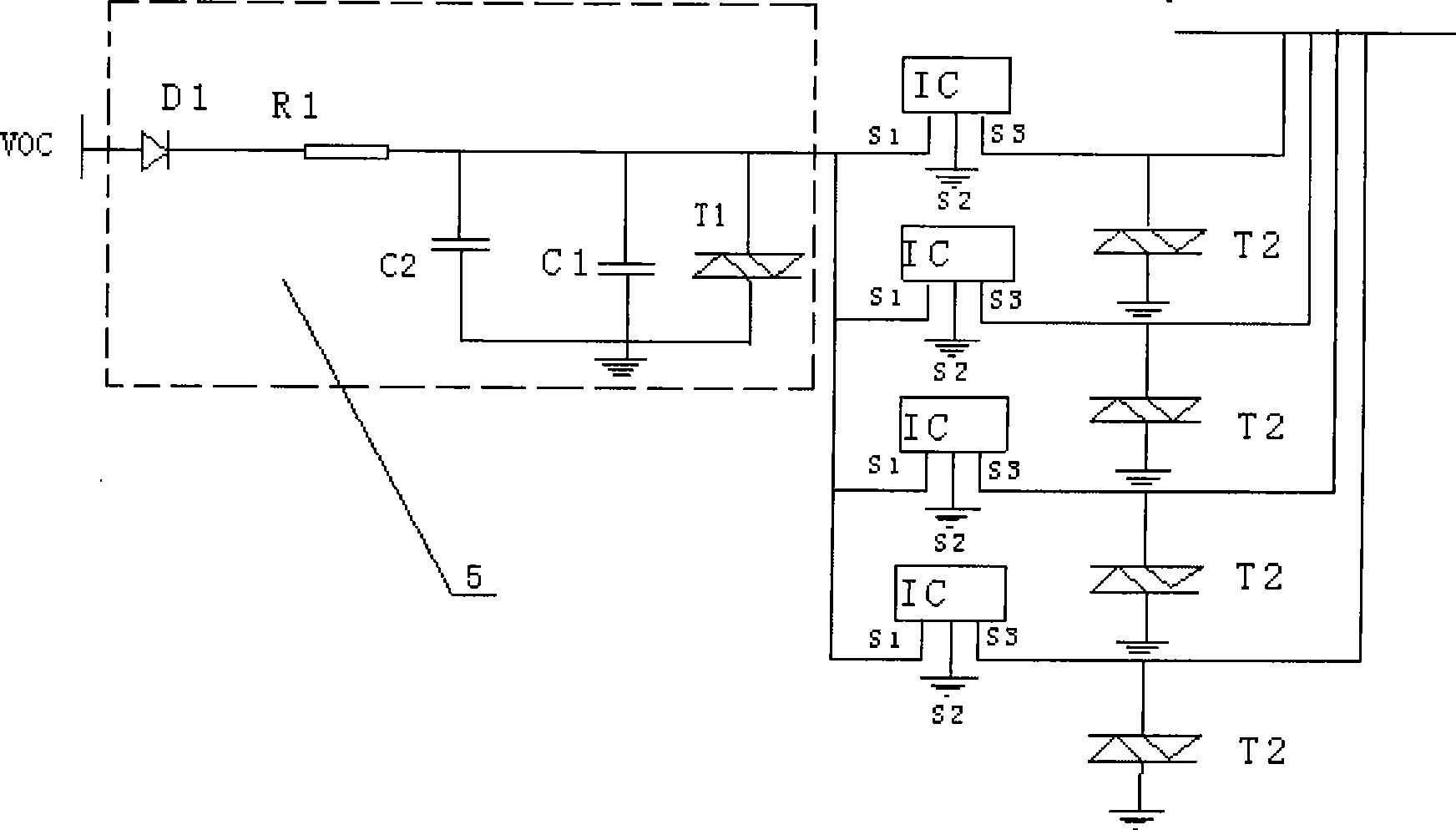
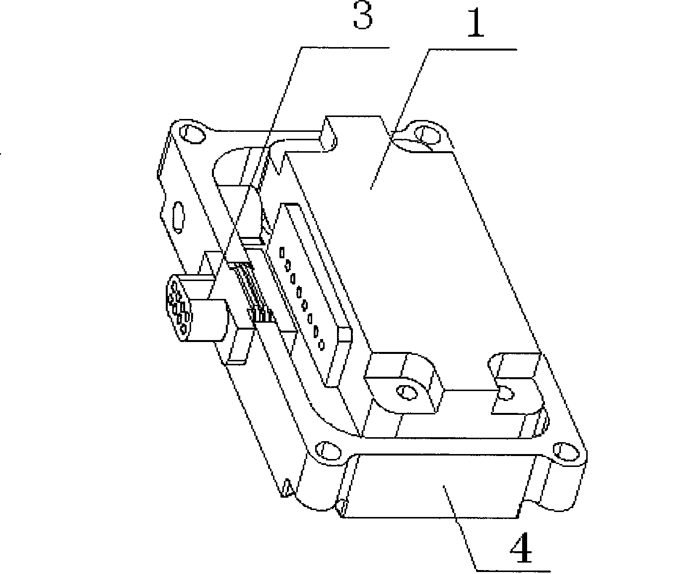
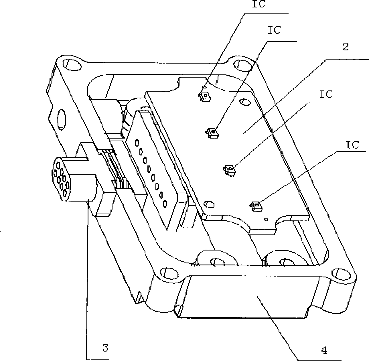
[0014] see figure 1 , image 3 and Figure 4 , there are four switch Hall integrated circuit ICs on the circuit board, each of the four Hall integrated circuit ICs has three pins, namely pin S1, pin S2 and pin S3, and the four pins S1 are connected to the same power supply The protection circuit is connected. In the power protection circuit, the anode of the diode D1 is connected to the DC power supply, the cathode of the diode D1 is connected to the resistor R1, the other end of the resistor R1 is connected to the pin S1, and the capacitor C1, the capacitor C2 and the TVS tube T1 are respectively connected to the pin Between S1 and ground; each of the four pins S2 is connected to ground. Each of the four pins S3 leads to two channels, one of which is connected to a TVS tube and then connected to the ground, and one of which is used as a ...


PUM


Abstract

The invention discloses a Hall gear position senor, which comprises an inner shell, a circuit board and Hall chips arranged on the circuit board, wherein the Hall chips are Hall integrated circuits IC and are tightly attached to the inner wall of the inner shell, the number of the Hall chips is the same as that of vehicle gear positions and the Hall chips are connected in parallel with the vehicle gear positions. Each Hall integrated circuit has three pins S1, S2 and S3, the pin S1 is connected with a power supply, the pin S2 is earthed, and the pin S3 is a signal output end. The sensor realizes point to point detection of gear-selecting gear positions, is accurate in performance, high in sensitivity, quick in response time, high in reliability, small in influence of environmental change, simple in structure, convenient in installation and long in service life, has shock-resistance, impact-resistance, electromagnetic interference-resistance, waterproof and dustproof capabilities, and is particularly suitable for monitoring gear positions in an automotive electrically-controlled mechanical automatic transmission and a pneumatic automatic gear box.

Description

technical field [0001] The invention relates to a gear position sensor, in particular to a non-contact Hall gear sensor. Background technique [0002] The task of the automobile transmission is to transmit power, and change the gear ratio during the power transmission process to adjust or change the characteristics of the engine, and at the same time adapt to different driving requirements through speed change. Manually operated stepped transmissions change suddenly in speed when shifting gears, often causing the engine to be in an unsteady state, so that the car emits a lot of harmful substances and causes serious pollution. To ensure that the engine is in good working condition during driving, it is very important to develop AMT. Starting and shifting are the main content of the control function. The driver transmits control signals to the electronic control unit (ECU) through the accelerator pedal and the joystick; the electronic control unit collects the gear selection ...

Claims


Application Information

Patent Timeline
Patent Type & Authority Applications(China)
IPC IPC(8): G01B7/00F16H63/42
Inventor 李占江任钢张烁宋志明涂平华
Owner NANJING AOLIAN AE&EA
Learn More