
High power LED lamp heat conducting and heat radiating device, heat conducting base and producing technique

A technology of LED lamps and manufacturing process, which is applied to cooling/heating devices of lighting devices, lighting devices, semiconductor devices, etc., and can solve the problems of not having a protective layer, affecting the heat conduction speed of the heat conduction base, and large volume, etc., to achieve expanded application Range, improved heat dissipation effect, high thermal conductivity effect

Inactive Publication Date: 2009-08-19
DONGGUAN XIANGLONG ENERGY TECH
View PDF0 Cites 17 Cited by
  • Summary
  • Abstract
  • Description
  • Claims
  • Application Information

AI Technical Summary

Problems solved by technology

However, due to the low hardness and low surface strength of graphite itself, graphite products are easily broken or worn during application, and graphite products cannot be directly welded to metal products, thus limiting the application of graphite products
[0003] In recent years, in order to take advantage of the good electrical and thermal conductivity of graphite, some manufacturers have adopted graphite as the heat conduction base of the heat sink. This heat conduction base is cut or extruded into a cuboid shape for CPU (central processing unit) The heat conduction of the product can quickly conduct the heat of CPU and other products to the heat sink made of copper and aluminum alloy. Compared with the traditional copper and aluminum alloy heat conduction base, this heat conduction base made of pure graphite The base not only has good thermal conductivity, but also has the characteristics of light weight and low cost. However, because the surface of this thermally conductive base made of graphite has no protective layer, it is easy to be crushed or worn during production or application. , affecting the heat conduction speed of the heat conduction base
[0004] Existing high-power LED lamps are mainly composed of a housing, an LED chip, a driver for driving the LED chip, a reflective cup covering the LED chip, a lens at the opening of the reflective cup, a heat-conducting substrate for fixing the LED chip, and The heat conduction base and the heat dissipation device made of copper and aluminum alloy are composed of the heat conduction base and the heat dissipation device constitute the heat conduction heat dissipation device of the LED lamp, the heat conduction substrate is fixed on the bottom of the heat conduction base, and the heat dissipation device is fixed on the At the top of the heat conduction base, when the LED chip is working for lighting, the heat generated by the LED chip is transmitted to the heat conduction base through the heat conduction base, and then transmitted to the heat sink by the heat conduction base, and finally the heat is naturally dissipated to the air by the heat sink Among them, the heat conduction base made of copper and aluminum alloy has large volume, heavy weight, and high material cost, while the heat sink made of copper and aluminum alloy is not only large in size, heavy in weight, and high in material cost. And it mainly uses the natural heat dissipation of the air, so the heat dissipation effect is not ideal.
Especially with the increase in the number of LEDs in high-power LED lamps and the development of high-power, high-brightness integrated LED chips, etc., the heat generated by high-power LED lamps is gradually rising. For example, some power exceeds 100 watts. The integrated LED chip has a heat dissipation area of ​​only 4 square centimeters. Therefore, it is difficult for the heat dissipation device of the existing high-power LED lamps to meet the heat dissipation requirements of high-power LED lamps with a power exceeding 100 watts.

Method used


Image

  • High power LED lamp heat conducting and heat radiating device, heat conducting base and producing technique
  • High power LED lamp heat conducting and heat radiating device, heat conducting base and producing technique
  • High power LED lamp heat conducting and heat radiating device, heat conducting base and producing technique

Examples


Embodiment 1

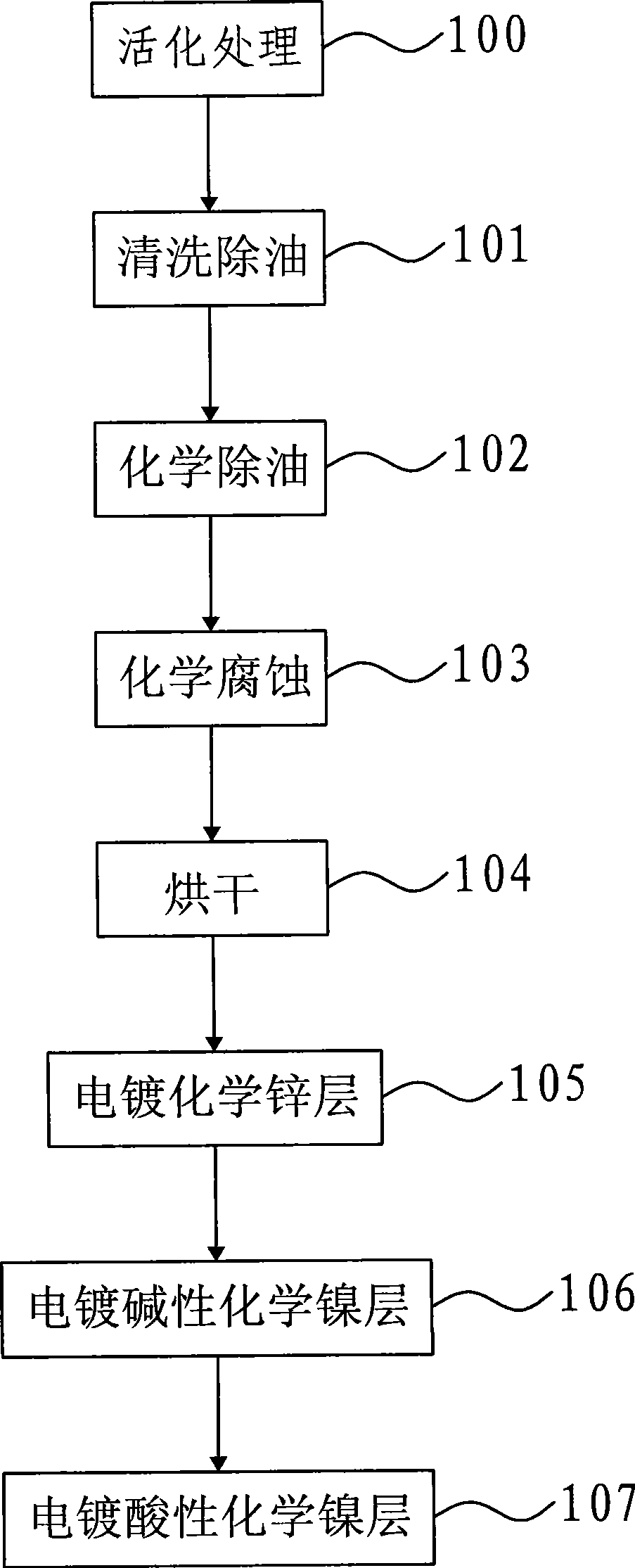
[0041] Below in conjunction with accompanying drawing, the present invention will be further described, please refer to figure 1, is graphite surface electroplating manufacturing process of the present invention. As shown in step activation treatment 100, first the processed graphite product is put into the activation treatment solution for soaking, that is, the graphite product has been cut into shape or punched according to the requirements, and then soaked in the activation treatment solution to control the degree of immersion. Time is 10~15 minutes, until the surface of graphite product is gray ink color; Wherein, the composition of the activation treatment solution of the present embodiment is: nickel sulfate 24~30g / L, hydroxyethylidene diphosphonic acid 40~50g / L, Stabilizer 25~30mL / L, surplus is water; Described activation treatment liquid is under normal temperature (being 25 ℃), adjusts pH value with sodium hydroxide solution and is greater than 12; The stabilizer of t...

Embodiment 2

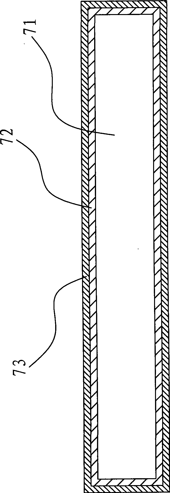
[0050] Please refer to figure 2 , is the graphite thermal conduction base that the present invention adopts the graphite surface electroplating manufacturing process of embodiment one to make, and it comprises graphite product 71, and the surface electroplating of described graphite product 71 has a chemical zinc layer 72, and the surface electroplating of chemical zinc layer 72 There is an chemical nickel layer 73; wherein, the chemical zinc layer 72 and the chemical nickel layer 73 are all formed on the surface of the graphite product 71 in the mode of electroless plating, and the effect of the chemical zinc layer 72 is to increase the adhesive force of the graphite product 71 surface, so that The outermost chemical nickel layer 73 can have good adhesion; because the chemical zinc layer 72 and the chemical nickel layer 73 electroplated on the graphite product 71 surface are all very thin, and the thickness of the chemical nickel layer 73 is 25~30 microns, so The chemical zi...

Embodiment 3

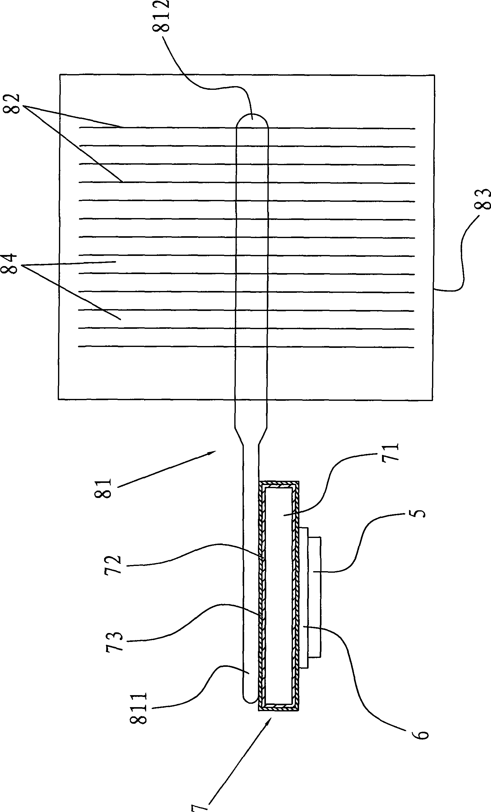
[0052] Please refer to image 3 , for the present invention adopts the heat conduction and heat dissipation device of the high-power LED lamp of the above-mentioned embodiment 2 graphite heat conduction base, it comprises above-mentioned graphite heat conduction base 7, heat dissipation device, graphite heat conduction base 7 is fixed on the heat conduction substrate 6 of LED lamp The top of the heat sink is fixed on the top of the graphite heat conduction base 7; according to the above description, the graphite heat conduction base 7 includes a graphite product 71, and the surface of the graphite product 71 is electroplated with a chemical zinc layer 72, and the surface of the chemical zinc layer 72 is electroplated There is an chemical nickel layer 73, wherein, the chemical zinc layer 72 and the chemical nickel layer 73 are all formed on the surface of the graphite product 71 by means of electroless plating, and the effect of the chemical zinc layer 72 is to increase the adhe...


PUM

PropertyMeasurementUnit
Thicknessaaaaaaaaaa
Strengthaaaaaaaaaa
Densityaaaaaaaaaa

Abstract

The invention discloses a heat-conduction and heat-dissipation device for a large-power LED luminaire, a heat-conduction base and a preparation process. The invention provides a graphite heat-conduction base which comprises a graphite product; the surface of the graphite product is electroplated by a chemical zinc layer; and the surface of the chemical zinc layer is electroplated by a chemical nickel layer. When the graphite heat-conduction base is being produced or applied, the chemical nickel layer of the outermost layer can protect the surface of the graphite product, thus leading the graphite product not easy to be damaged by pressure or abraded. The invention also provides a heat-conduction and heat-dissipation device for the large-power LED luminaire, comprising the graphite heat-conduction base and a heat dissipation device; the graphite heat-conduction base is fixedly arranged on the top end of the heat-conduction substrate of the large-power LED luminaire; and the heat dissipation device is fixedly arranged on the top end of the graphite heat-conduction base. The heat-conduction and heat-dissipation device for the large-power LED luminaire has the advantages of small volume, light weight, low cost, good heat-dissipation effect, good welding performance, good wearability, higher hardness, high electric-conduction and heat-conduction and the like.

Description

Technical field: [0001] The invention relates to a graphite surface electroplating manufacturing process, a graphite heat conduction base manufactured by the process, and a high-power LED (LightEmitting Diode, light emitting diode) lamp heat conduction and heat dissipation device including the graphite heat conduction base. Background technique: [0002] Because graphite has the characteristics of high temperature resistance, light weight, low cost, good electrical and thermal conductivity, chemical stability, and thermal shock resistance, it has been widely used in industry. However, due to the low hardness and low surface strength of graphite itself, graphite products are easily broken or worn during application. Moreover, graphite products cannot be directly welded to metal products, thus limiting the application of graphite products. [0003] In recent years, in order to take advantage of the good electrical and thermal conductivity of graphite, some manufacturers have a...

Claims


Application Information

Patent Timeline
IPC IPC(8): F21V29/00H01L23/373H01L33/00C25D3/00F21Y101/02F21V29/51F21V29/76F21V29/85F21V29/89F21Y115/10
Inventor 刘祥龙
Owner DONGGUAN XIANGLONG ENERGY TECH
Learn More