
Scanning exposure system and method of photo-etching machine

A technology of scanning exposure and exposure field, used in microlithography exposure equipment, photolithography process exposure devices, etc.

Active Publication Date: 2011-02-02
SHANGHAI MICRO ELECTRONICS EQUIP (GRP) CO LTD
View PDF0 Cites 0 Cited by
  • Summary
  • Abstract
  • Description
  • Claims
  • Application Information

AI Technical Summary

Problems solved by technology

However, these methods are all based on the unidirectional scanning exposure method, which can only improve the dose uniformity of the exposure field in the scanning direction (Y direction), and cannot change the dose uniformity in the non-scanning direction (X direction)—the slit integral uniformity, so that The uniformity of the slit integration becomes one of the main factors restricting the performance of the exposure dose system of the lithography machine

Method used


Image

  • Scanning exposure system and method of photo-etching machine
  • Scanning exposure system and method of photo-etching machine
  • Scanning exposure system and method of photo-etching machine

Examples


Embodiment Construction

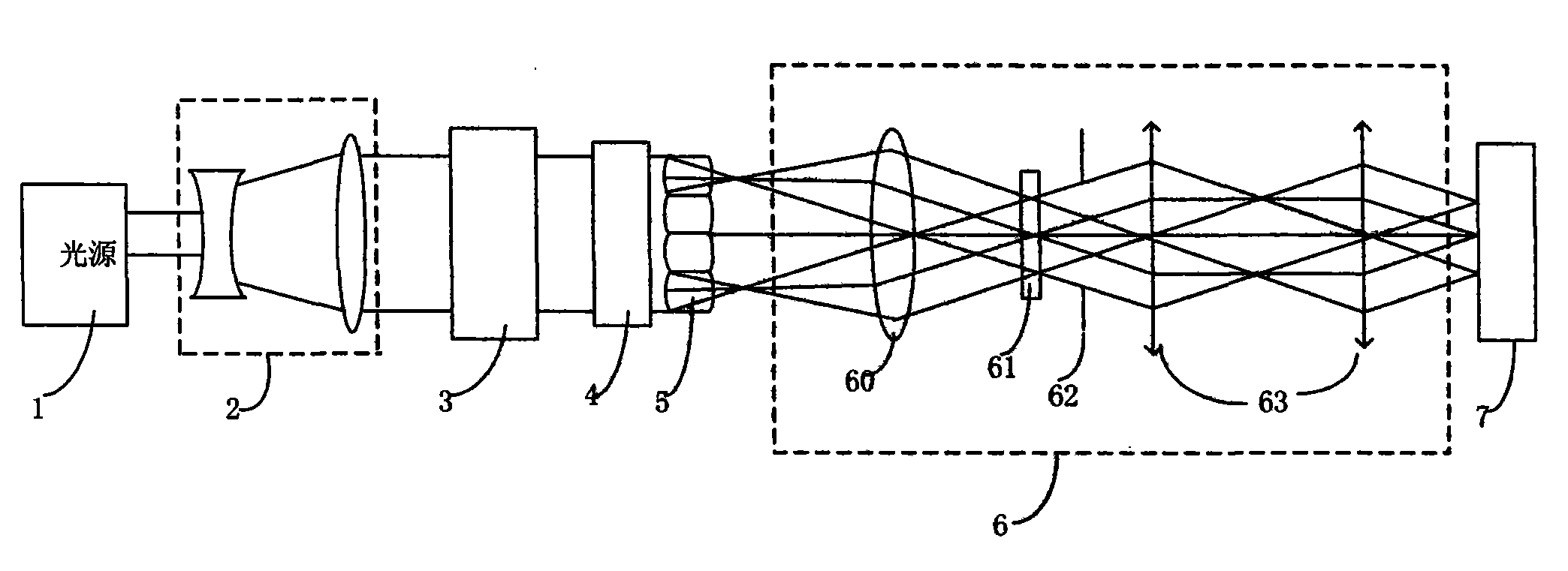
[0035] see Figure 4 , Figure 4 It is a schematic diagram of the field profile of the first scanning exposure and the scanning exposure effect in the scanning exposure system embodiment of the lithography machine of the present invention. When the beam rotating mirror group 4 moves away from the position of the optical path 10, the optical homogenizer 5 returns to its original position, the knife edges on the variable slit 62 are all opened, and a field profile 11 of 22mm*22mm is obtained on the silicon plane, wherein the scanning direction The width in the Y direction is 22mm, and a continuous trapezoidal beam distribution is formed in the scanning direction. The top width of the scanning direction is 19mm and the distribution is approximately uniform along the non-scanning direction. The uniformity of the slit integration in the non-scanning direction is not good.

[0036] see Figure 5 , Figure 5 It is a schematic diagram of the outline of the field of view and the sca...


PUM


Abstract

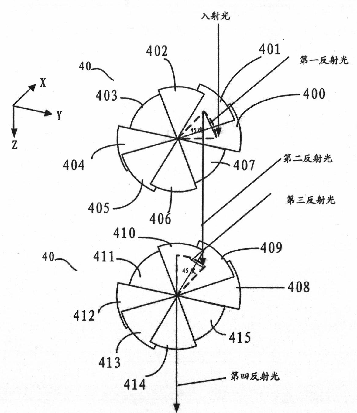
The invention provides a scanning exposure system of photoetching machine, comprising a light source and a cylinder lens, a zoom lens set, an optical uniform device, a coupling light set, a mask plate, an objective lens and a workpiece platform which are arranged in order along the light path formed by the light source emergent light beam, a light beam rotating lens set is arranged between the zoom lens set and the optical uniform device and composed of a plurality of sets of optical elements. When scanning exposure, firstly the light beam rotating lens set is transferred into the light path after scanning and exposing the exposure field zone, then the exposure field zone is scanned and exposed again, the rotating lens set is shifted away after completing the scanning exposure, so that the dose homogeneity of exposure field Y direction is improved, and the dose homogeneity of X direction is also improved, thereby improving the system performance of the exposure dose and increasing thehomogeneity of the photoetching line width.

Description

technical field [0001] The invention relates to a semiconductor device and a method thereof, in particular to a scanning exposure system of a photolithography machine and a scanning exposure method thereof. Background technique [0002] The core of modern microelectronics technology is integrated circuit production, and the development of integrated circuit production must be supported by semiconductor equipment. In the current integrated circuit production equipment, lithography equipment occupies the most core position. After the lithography technology has gone through several major technical development stages of contact type, proximity type, projection type, scanning type and stepping type, it transitions to stepping and scanning type. [0003] The three core indicators of lithography machines are line width uniformity, overlay accuracy and productivity. Line width uniformity is an important core index of a lithography machine, and the performance of the dose system and...

Claims


Application Information

Patent Timeline
Patent Type & Authority Patents(China)
IPC IPC(8): G03F7/20
Inventor 张俊罗鸣
Owner SHANGHAI MICRO ELECTRONICS EQUIP (GRP) CO LTD
Learn More