Method for moulding disc grade glass device by using micro-mould
A wafer-level, micro-mold technology, applied in glass forming, glass manufacturing equipment, manufacturing tools, etc., can solve the problems of low processing efficiency, large structural shape and size limitations, low cost, etc., and achieve high bonding strength. , good sealing effect
- Summary
- Abstract
- Description
- Claims
- Application Information
AI Technical Summary
Problems solved by technology
Method used
Image
Examples
Embodiment 1
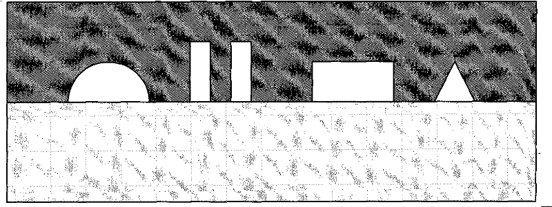
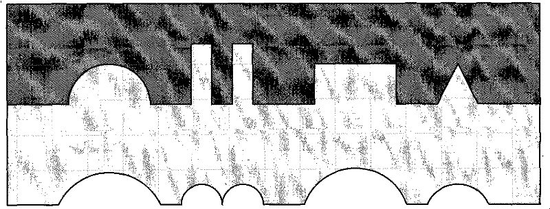
[0028] A method for forming a wafer-level glass device with a micro-mold, characterized in that it comprises the following steps:
[0029] The first step is to etch a deep cavity of a mold with a specific structure on the polished silicon wafer in the microelectronics processing technology. In this embodiment, the first step of the microelectronics processing technology is: wet etching process, dry plasma etching process , reactive ion etching or deep reactive ion etching.
[0030] In the second step, the above-mentioned silicon wafer and the Pyrex7740 glass wafer are bonded in a vacuum environment, and the vacuum degree can be: 10 -6 10Pa, for example, 10 -5 Pa, 10 -4 Pa, 10 -3 Pa, 10 -1 Pa, 2Pa, 4Pa, 8Pa, so that the above-mentioned specific structure mold deep cavity on the silicon wafer forms a sealed cavity, and the bonding can adopt anodic bonding process, or fusion bonding and other processes, preferably anodic bonding process, The process conditions are: temperatu...
Embodiment 2
[0036] A method for forming a wafer-level glass device with a micro-mold, comprising the following steps:
[0037] In the first step, a silicon wafer (such as a 4-inch wafer) is etched to form a specific microcavity structure as a mold using a silicon micromachining process, and the micromachining process of the microcavity structure on the silicon original chip is a wet etching process, or One of the dry ICP etching process, RIE or DRIE, the pattern can be a square or circular microcavity array, or various patterns. In fact, from a three-dimensional perspective, the specific microcavity structure is a deep groove carved on a silicon wafer, and from a two-dimensional perspective, it is a pattern.
[0038] In the second step, the above-mentioned silicon wafer and the same polished Pyrex7740 glass wafer are less than 1*10 -2 Anodic bonding is carried out under the atmosphere of Pa, for example, the pressure is 0.01Pa, 0.005Pa, 0.001Pa, so that the Pyrex7740 glass and the silico...
Embodiment 3
[0044] A method for forming a wafer-level glass device using a micro-mold with a large aspect ratio glass surface microstructure, comprising the following steps:
[0045] The first step is to use the DRIE etching method to etch a specific mold structure on a 4-inch silicon wafer (in fact, from a three-dimensional view, it is a deep groove on the silicon wafer, and a two-dimensional view is a pattern), and the aspect ratio is 50. : 1, silicon wafers are polished.
[0046] In the second step, the above-mentioned silicon wafer and the same size (4 inches) Pyrex7740 glass wafer are placed in a 1*10 -3 Anodic bonding is carried out under a vacuum of Pa, so that the Pyrex7740 glass and the silicon mold cavity form a sealed cavity. The bonding surface is cleaned and polished according to the bonding requirements before anodic bonding to keep a high degree of cleanliness and minimal surface roughness.
[0047] The third step is to heat the above-mentioned bonded wafer to 850°C under ...
PUM
 Abstract
Description
Claims
Application Information
 - R&D
- Intellectual Property
- Life Sciences
- Materials
- Tech Scout
- Unparalleled Data Quality
- Higher Quality Content
- 60% Fewer Hallucinations
Browse by: Latest US Patents, China's latest patents, Technical Efficacy Thesaurus, Application Domain, Technology Topic, Popular Technical Reports.
© 2025 PatSnap. All rights reserved.Legal|Privacy policy|Modern Slavery Act Transparency Statement|Sitemap|About US| Contact US: help@patsnap.com


