Alloy for liquid-phase diffusion bonding
一种液相扩散、合金的技术,应用在焊接介质、焊接设备、金属加工设备等方向
- Summary
- Abstract
- Description
- Claims
- Application Information
AI Technical Summary
Problems solved by technology
Method used
Image
Examples
specific Embodiment approach
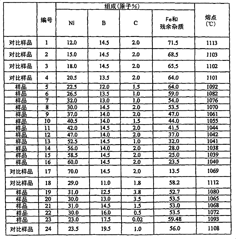
[0047] The effects of the present invention are explained below based on Examples and Comparative Examples of the present invention. In Example 1 of the first invention, master alloys of each composition shown in Table 1 below were cast using electrolytic Fe, electrolytic Ni, B, and C each having a purity of 99.9% by mass in an argon atmosphere. Each master alloy was remelted in a quartz crucible with a slot opening of 25 mm wide and a gap of 0.4 mm and sprayed through the slot onto the running surface of a copper cooling roll with a peripheral speed of 25 m / sec to quench to form a 25 μm thick non-ferrous metal. Shaped foil. The melting point is then determined from the endothermic or exothermic temperature upon melting / solidification by heating and cooling the foil. The results are also shown in Table 1.
[0048] Table 1
[0049]
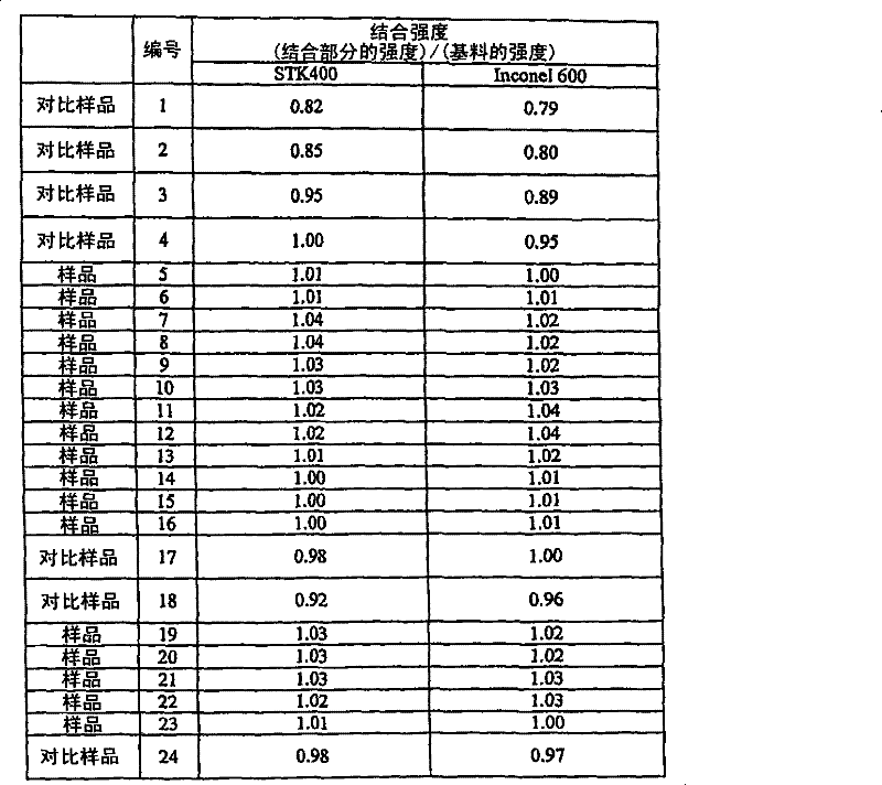
[0050] Using the bonding alloy foils of Examples and Comparative Examples prepared above, bonding tests were performed and bonding strength ...
Embodiment 2
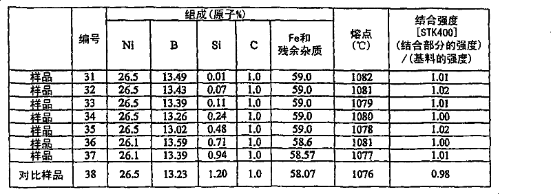
[0057] Example 2 of the first embodiment of the present invention is explained below. In this Example 2, the master alloys of each composition shown in Table 3 below were cast using electrolytic Fe, electrolytic Ni, B, Si, and C each having a purity of 99.9% by mass in an argon atmosphere. Each mother alloy foil was prepared in the same manner as in Example 1 above. In the same manner as in Example 1, a bonding test was performed and the bonding strength was measured. Fe-based alloy material STK 400 was used as the base material to be joined. The results are shown in Table 3 below.
[0058] table 3
[0059]
[0060] As shown in Table 3, the bonding alloys of sample numbers 31 to 37, the concentration of Si was kept within the range of the present invention, indicating that the ratio (strength of the bonding portion) / (strength of the base material) was 1.00 or more, that is, Sample Nos. 31-37 were excellent in bonding strength. In contrast, in the bonding alloy of Compa...
Embodiment 3
[0062] Example 3 of the first embodiment of the present invention is explained below. In this Example 3, master alloys of each composition shown in Table 4 below were cast using electrolytic Fe, electrolytic Ni, B, Si, C, W, Mo, and Cr each having a purity of 99.9 mass % under an argon atmosphere. Each mother alloy foil was prepared in the same manner as in Example 1 above. In the same manner as in Example 1, a bonding test was performed and the bonding strength was measured. Fe-based alloy material STK 400 was used as the base material to be joined. The results are shown in Table 4 below.
[0063] Table 4
[0064]
[0065] As shown in Table 4 above, Comparative Sample Nos. 41 to 43 in which the concentrations of each of the main components Fe and Ni were outside the range of the present invention hardly lowered the melting point even if Mo was added within the concentration range of the present invention, and ( The ratio of the strength of the joint part) / (strength of ...
PUM
| Property | Measurement | Unit |
|---|---|---|
| melting point | aaaaa | aaaaa |
| particle diameter | aaaaa | aaaaa |
| melting point | aaaaa | aaaaa |
Abstract
Description
Claims
Application Information
 - R&D
- Intellectual Property
- Life Sciences
- Materials
- Tech Scout
- Unparalleled Data Quality
- Higher Quality Content
- 60% Fewer Hallucinations
Browse by: Latest US Patents, China's latest patents, Technical Efficacy Thesaurus, Application Domain, Technology Topic, Popular Technical Reports.
© 2025 PatSnap. All rights reserved.Legal|Privacy policy|Modern Slavery Act Transparency Statement|Sitemap|About US| Contact US: help@patsnap.com


