
Electronic cigarette atomizer and electronic cigarette using the same

a technology of electronic cigarettes and atomizers, which is applied in the direction of heating types, container discharging methods, separation processes, etc., can solve the problems of inability to adjust the amount of smoke generated by electronic cigarettes atomizers, the inability of electronic cigarettes atomizers to normally work, and the inability to generate smoke. large, prevent the condensation of tobacco juice, and generate a large amount of smoke

Inactive Publication Date: 2015-07-16
HUIZHOU KIMREE TECH
View PDF10 Cites 158 Cited by
  • Summary
  • Abstract
  • Description
  • Claims
  • Application Information

AI Technical Summary

Benefits of technology

The present patent application describes an electronic cigarette atomizer that has several advantages. Firstly, it includes multiple coaxial atomizing assemblies that can generate a large amount of smoke when used. The smoke generated by each assembly enters the mouth cavity of the user through intercommunicated smoke channels, resulting in a high concentration of smoke that enhances the user's experience. Secondly, the coaxial atomizing assemblies form a compact structure without additional space containing air, resulting in a high concentration of smoke that can be inhaled by the user with low smoking intensity. Lastly, the atomizing assemblies are interconnected by detachable connecting structures, making it easy to assemble and replace them independently. Additionally, the user can adjust the amount of smoke by combining different atomizing assemblies containing tobacco juice in different tastes, enhancing their personalized needs.

Problems solved by technology

However, the electronic cigarette atomizer can only generate little smoke when it works.
Moreover, the amount of the smoke generated by the electronic cigarette atomizer cannot be adjusted.
Furthermore, if the atomizing assembly malfunctions, the electronic cigarette atomizer cannot normally work.

Method used


Image

  • Electronic cigarette atomizer and electronic cigarette using the same
  • Electronic cigarette atomizer and electronic cigarette using the same
  • Electronic cigarette atomizer and electronic cigarette using the same

Examples


Embodiment Construction

[0057]In order to understand the technical features, purpose and the effect of the present invention more clearly, the preferred specific embodiments of the present invention will be described referring to the drawings.

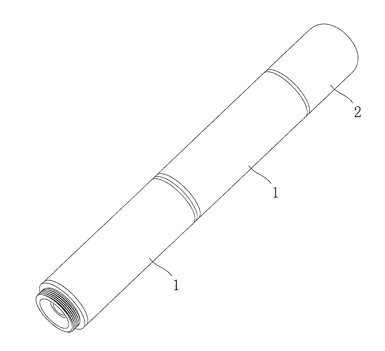
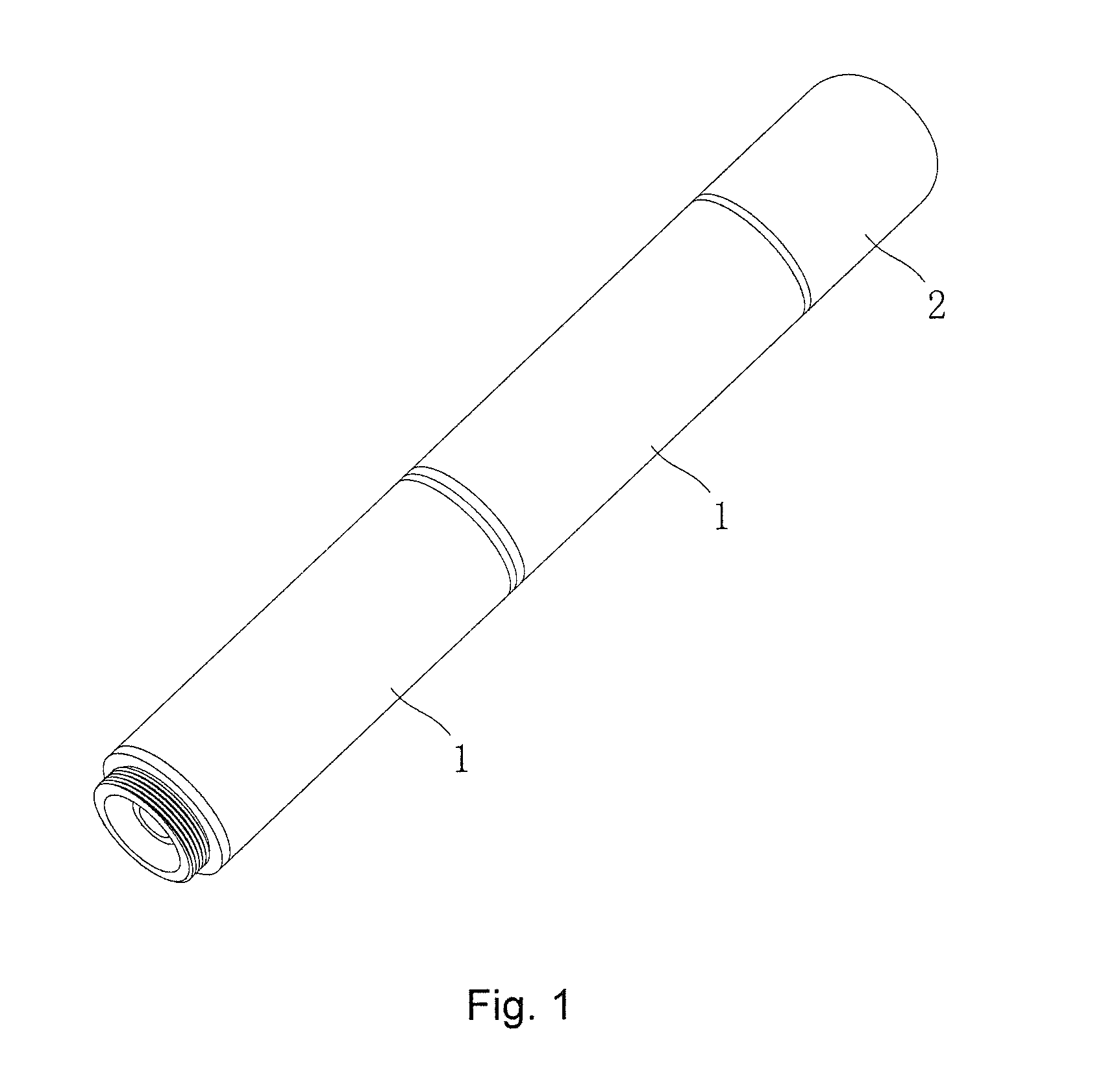
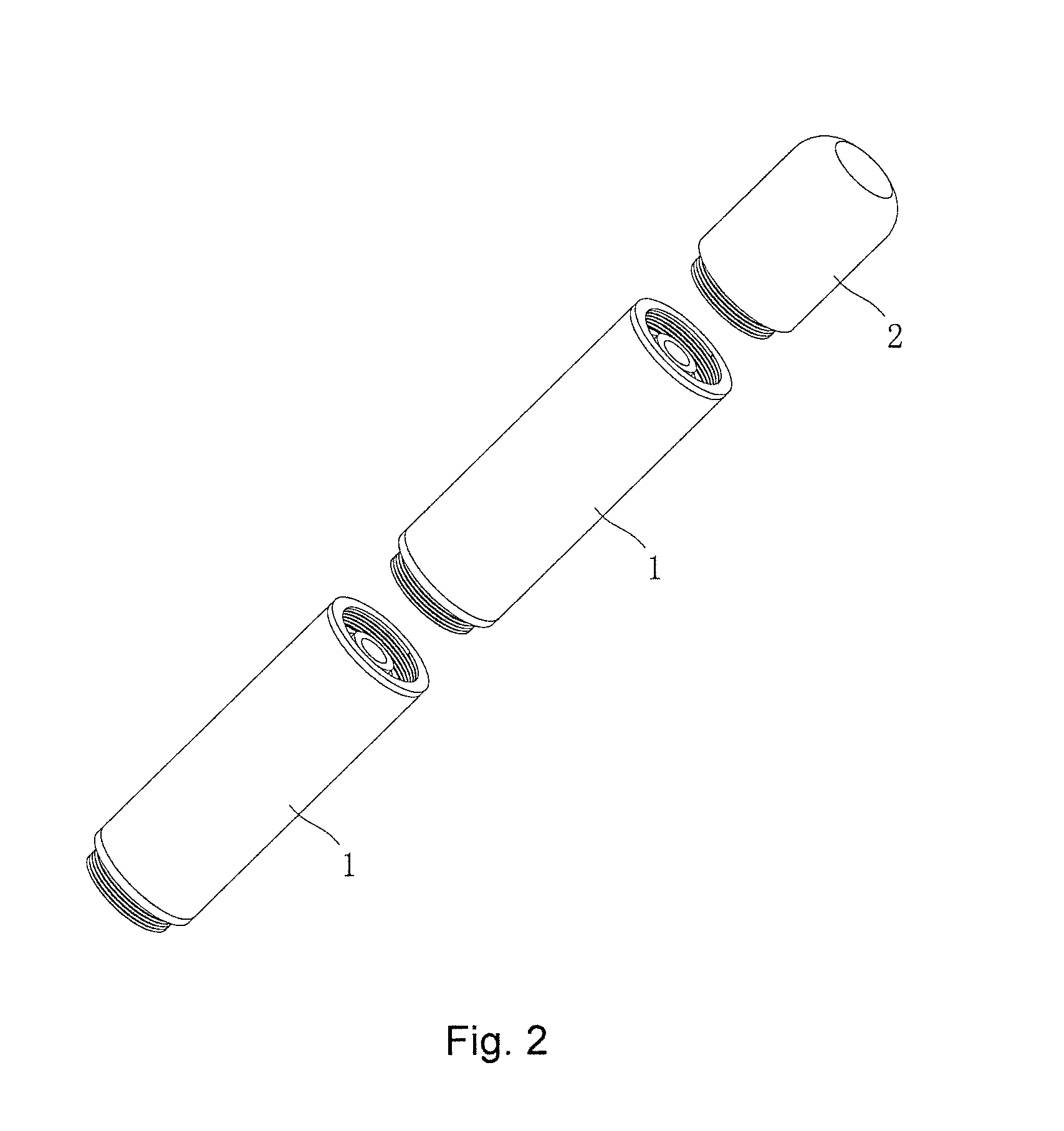
[0058]As shown in FIG. 1, FIG. 2, FIG. 3, FIG. 4, FIG. 5, a first preferred embodiment of the present application provides an electronic cigarette atomizer, which includes a plurality of atomizing assemblies 1 and a suction nozzle 2. Wherein each atomizing assembly 1 includes a heating wire 12, and a guide rope 101 configured to transmit tobacco juice to the heating wire 12 so as to use the heating wire 12 to atomize the tobacco juice. The heating wire 12 is entirely or partially received in a smoke channel 100 defined in the atomizing assembly 1. When the heating wire 12 works, the electronic cigarette atomizer generates smoke for being inhaled by users; and the smoke is discharged via the smoke channel 100. In this embodiment, the number of the atomizing assemblies ...


PUM


Abstract

The present application discloses an electronic cigarette atomizer and an electronic cigarette using the electronic cigarette atomizer. The electronic cigarette atomizer comprises a plurality of atomizing assemblies, and each atomizing assembly includes at least one heating wire and defines a smoke channel configured to discharge smoke. The atomizing assemblies are all coaxial and thereby form a string, and the smoke channels of every two adjacent atomizing assemblies communicate with each other. The heating wires of all the atomizing assemblies are electrically connected successively, and the heating wire of each atomizing assembly is entirely or partially received in the smoke channel of the atomizing assembly. Pluralities of detachable connecting structure are mounted between every two adjacent atomizing assemblies to detachably connect every two adjacent atomizing assemblies with each other.

Description

CROSS REFERENCE TO RELATED APPLICATIONS[0001]This application claims priority to International Application No. PCT / CN2014 / 070569, filed Jan. 14, 2014, which is hereby incorporated herein in its entirety by reference.FIELD OF THE INVENTION[0002]The present application relates to the field of daily electronic products, and more particularly, relates to an electronic cigarette atomizer and an electronic cigarette using the same.BACKGROUND OF THE INVENTION[0003]In the prior art, an electronic cigarette atomizer of an electronic cigarette usually includes only one atomizing assembly. The atomizing assembly usually includes an atomizing sleeve, a heating wire received in the atomizing sleeve, and a guide rope. The heating wire winds around the guide rope, and the guide rope is configured to transmit tobacco juice to the heating wire so as to use the heating wire to atomize the tobacco juice. The atomizing sleeve defines a smoke channel configured to discharge smoke generated by atomizing ...

Claims


Application Information

Patent Timeline
Patent Type & Authority Applications(United States)
IPC IPC(8): A24F47/00H05B3/03A24F15/015A24F40/10A24F40/30A24F40/40
CPCH05B3/03A24F47/008H05B3/06A24F40/10A24F40/30A24F15/015A24F40/40
Inventor LIU, QIUMING
Owner HUIZHOU KIMREE TECH
Learn More