Niobium solid electrolytic capacitor and its production method
A technology of solid electrolysis and manufacturing method, applied in solid electrolytic capacitors, electrolytic capacitors, capacitors, etc., can solve the problems of easy generation of leakage current, reduction of electrostatic capacitance, etc., to reduce leakage current, improve capacitance retention, simple and efficient manufacturing Effect
- Summary
- Abstract
- Description
- Claims
- Application Information
AI Technical Summary
Problems solved by technology
Method used
Image


Examples
Embodiment 1
[0047] step 1:
[0048] First, a niobium powder having a CV value of 150,000 [μF·V / g] as a product of capacitance and electrolytic voltage of the niobium sintered body after the electrolytic oxide film was formed was mixed with niobium monoxide powder. The mixing ratio was such that the content of niobium monoxide powder was 20% by weight relative to the total mass of the anode.
[0049] Hereinafter, unless otherwise specified, the CV value in each of the Examples and Comparative Examples is 150,000 [µF·V / g]. Here, as the CV value in the present invention, a value measured in accordance with EIAJ RC-2361A of the Japan Electronic Machinery Industries Association standard is used. However, in this measurement, a 30% by weight sulfuric acid solution was used as the measurement liquid, the measurement frequency was 120 Hz, and the superimposition of the bias voltage was omitted.
[0050] Step 2:
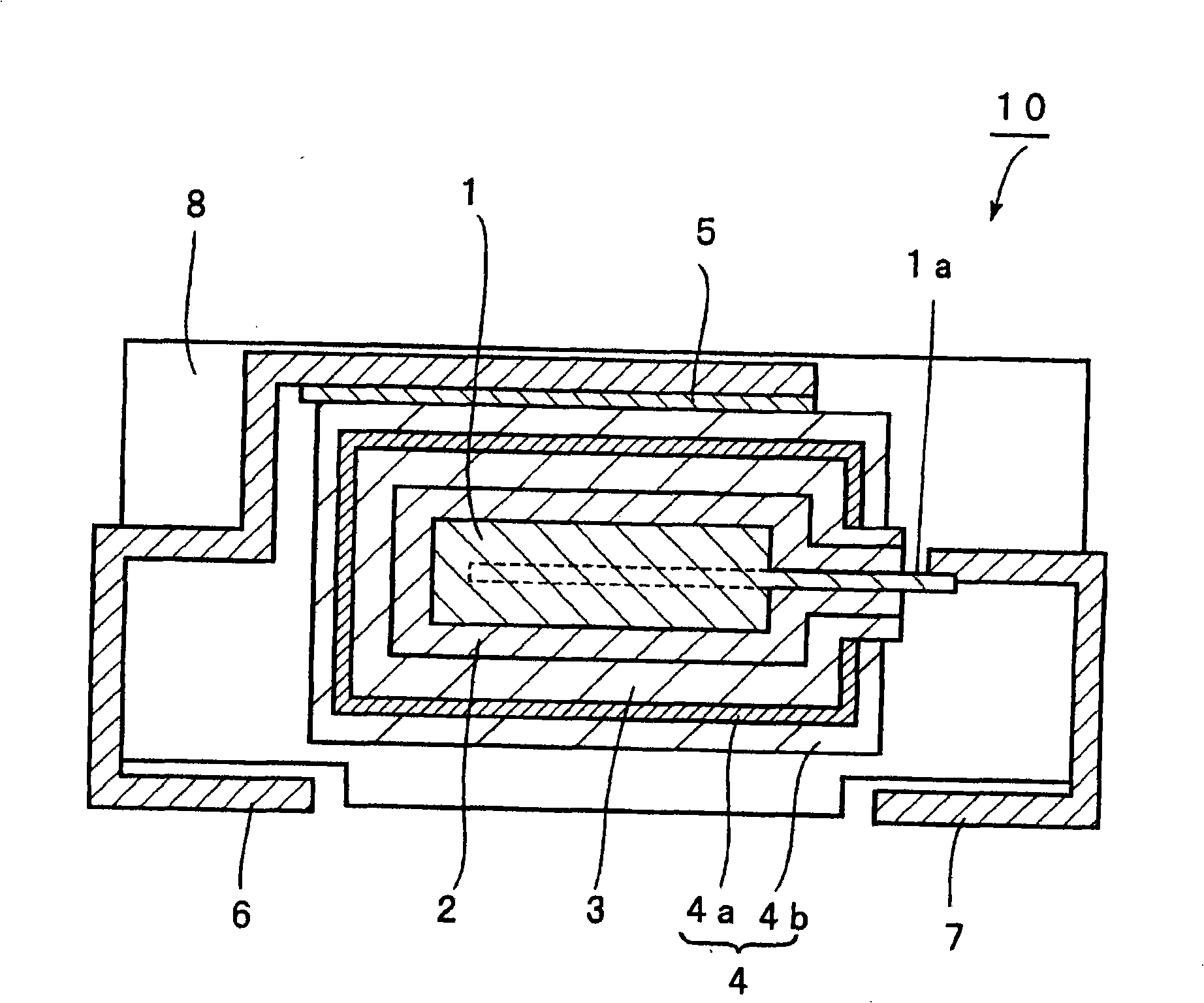
[0051] The anode 1 composed of a porous sintered body is formed by sintering the ...
Embodiment 2
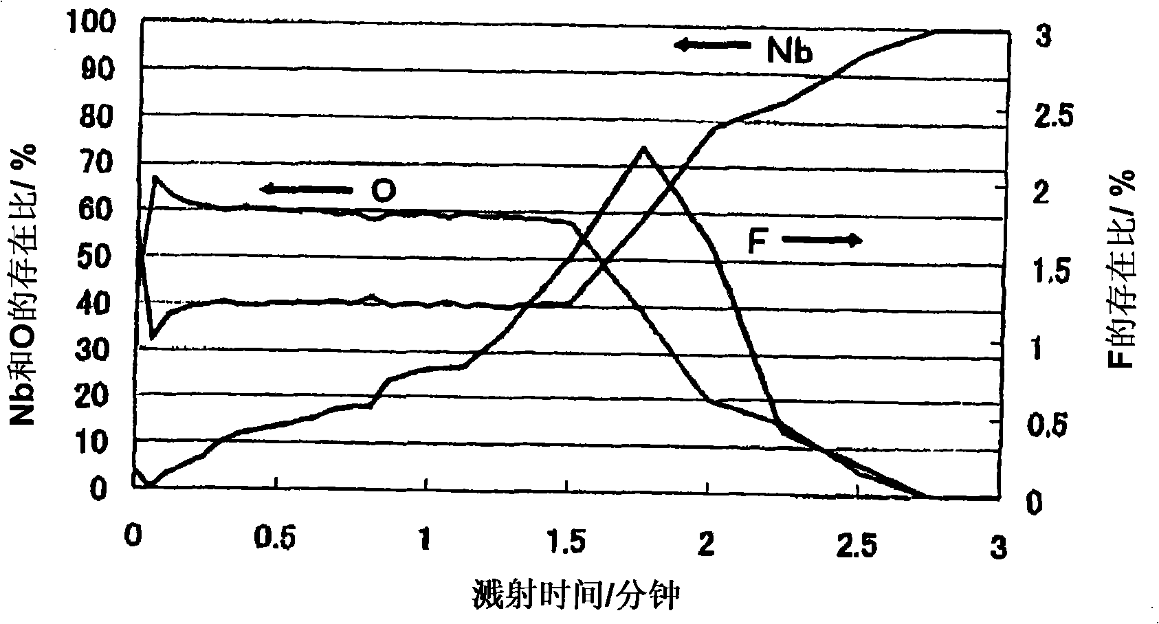
[0061] After the anodic oxidation using ammonium fluoride aqueous solution in step 2 of Example 1, anodic oxidation was performed again at 40° C. in 0.1% by weight phosphoric acid aqueous solution for two hours to form a dielectric layer. The composition of the formed dielectric layer was analyzed by XPS.
[0062] image 3 It is a graph showing the result of analyzing the composition of the dielectric layer by XPS.
[0063] image 3 In , the horizontal axis represents sputtering time (minutes), which corresponds to the thickness of the dielectric layer in the depth direction. The vertical axis on the left represents the abundance ratio (%) of Nb and O, and the vertical axis on the right represents the abundance ratio (%) of F and P.
[0064] Such as image 3 As shown, in this embodiment, P (phosphorus) exists near the surface of the dielectric layer. P is on the cathode side. When the depth of 10% of the maximum concentration of O is defined as the thickness of the diele...
Embodiment 3
[0087] A solid electrolytic capacitor A3 was produced in the same manner as in Example 1 except that the mixing ratio of the niobium monoxide powder in the mixture of niobium powder and niobium monoxide powder was 5% by weight.
PUM
 Abstract
Description
Claims
Application Information
 - R&D
- Intellectual Property
- Life Sciences
- Materials
- Tech Scout
- Unparalleled Data Quality
- Higher Quality Content
- 60% Fewer Hallucinations
Browse by: Latest US Patents, China's latest patents, Technical Efficacy Thesaurus, Application Domain, Technology Topic, Popular Technical Reports.
© 2025 PatSnap. All rights reserved.Legal|Privacy policy|Modern Slavery Act Transparency Statement|Sitemap|About US| Contact US: help@patsnap.com