Ceramic base compound material bolt preparation method
A composite material and ceramic-based technology, applied in the direction of screws, mechanical equipment, threaded fasteners, etc., can solve the problems of high cost and poor quality, and achieve the effect of reducing production costs and ensuring processing quality and strength
- Summary
- Abstract
- Description
- Claims
- Application Information
AI Technical Summary
Problems solved by technology
Method used
Image
Examples
Embodiment 1
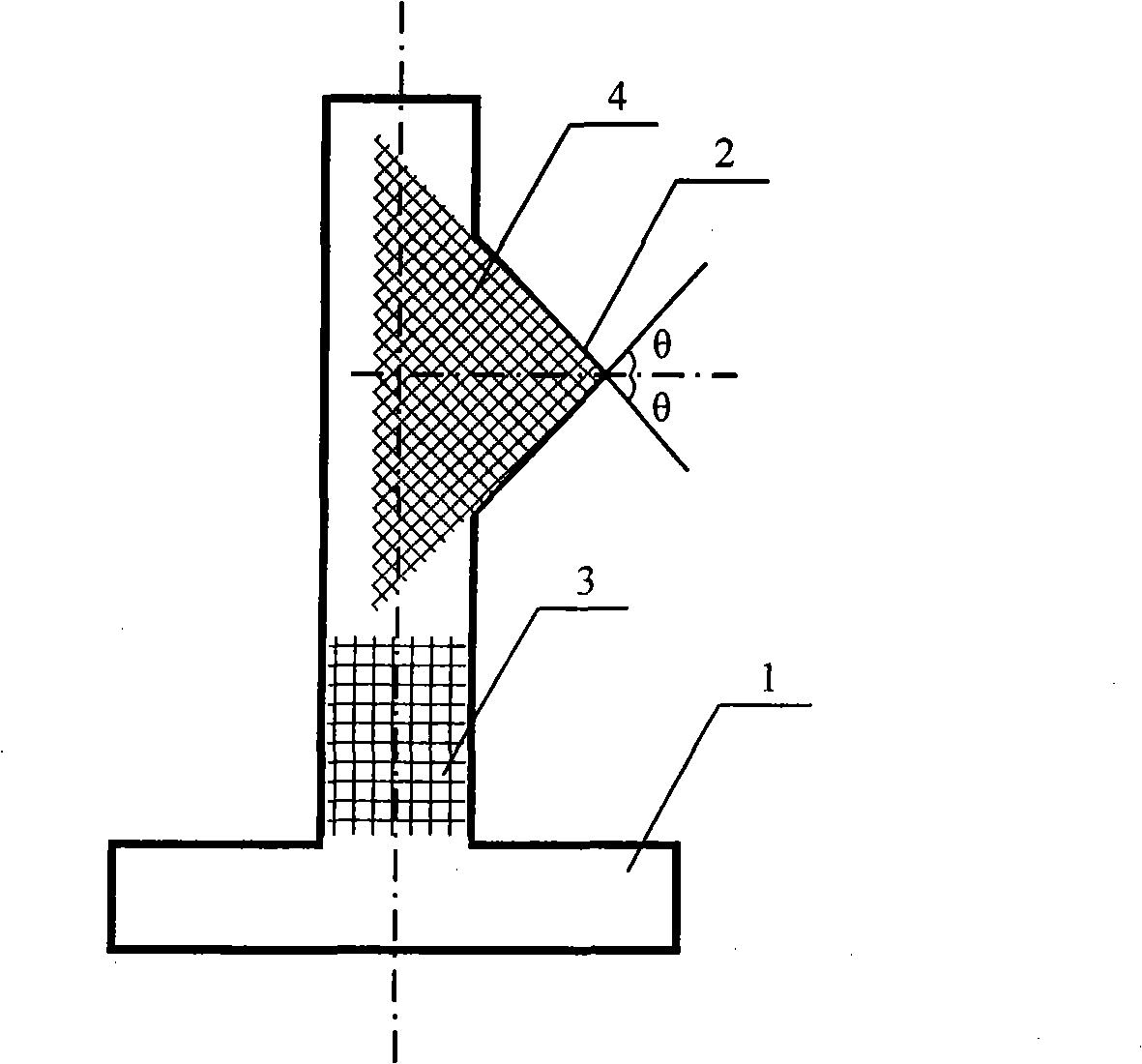
[0020] Example 1: Use 1K carbon fiber to lay the first layer at 0°, lay the second layer perpendicular to the first layer above it, and lay the third layer obliquely at +45° on the second layer, and then lay the Lay the fourth layer obliquely on top of the third layer at an angle of -45°, and alternately lay layers in this order, and prepare a carbon fiber two-dimensional plate prefabrication body according to the size of the required bolts. The normal ply fiber 3 is parallel to the center line of the screw rod of the bolt, and the oblique ply fiber 4 is parallel to the screw thread 2 surface of the bolt.
[0021] The pyrolytic carbon interface layer was deposited on the carbon fiber two-dimensional plate preform. The process conditions were: deposition temperature 800°C, pressure 0.2kPa, propylene flow rate 35ml / min, Ar gas flow rate 250ml / min, and deposition time 60h.
[0022] The silicon carbide substrate was deposited on the carbon fiber two-dimensional sheet deposited wit...
Embodiment 2
[0027] Example 2: Use 1K carbon fiber to lay the first layer according to 0°, lay the second layer perpendicular to the first layer above it, and lay the third layer obliquely on the second layer at an angle of +45°, and then lay the Lay the fourth layer obliquely on top of the third layer at an angle of -45°, and alternately lay layers in this order, and prepare a carbon fiber two-dimensional plate prefabrication body according to the size of the required bolts. The normal ply fiber 3 is parallel to the center line of the screw rod of the bolt, and the oblique ply fiber 4 is parallel to the screw thread 2 surface of the bolt.
[0028] The pyrolytic carbon interface layer was deposited on the carbon fiber two-dimensional plate preform. The process conditions were: deposition temperature 840°C, pressure 0.3kPa, propylene flow rate 28ml / min, Ar gas flow rate 270ml / min, and deposition time 45h.
[0029] The silicon carbide substrate was deposited on the carbon fiber two-dimension...
Embodiment 3
[0034] Example 3: Use 1K carbon fiber to pave the first layer according to 0°, lay the second layer perpendicular to the first layer on it, and lay the third layer obliquely on the second layer at an angle of +30°, and then lay the Lay the fourth layer obliquely on top of the third layer at an angle of -30°, and lay layers alternately in this order, and prepare a carbon fiber two-dimensional plate prefabricated body according to the size of the required bolts. The normal ply fiber 3 is parallel to the center line of the screw rod of the bolt, and the oblique ply fiber 4 is parallel to the screw thread 2 surface of the bolt.
[0035] The pyrolytic carbon interface layer was deposited on the carbon fiber two-dimensional plate prefabricated body. The process conditions were as follows: deposition temperature 870°C, pressure 0.3kPa, propylene flow rate 31ml / min, Ar gas flow rate 310ml / min, and deposition time 55h.
[0036] The silicon carbide substrate was deposited on the carbon ...
PUM
| Property | Measurement | Unit |
|---|---|---|
| breaking strength | aaaaa | aaaaa |
| tensile strength at break | aaaaa | aaaaa |
| tensile strength at break | aaaaa | aaaaa |
Abstract
Description
Claims
Application Information
 - R&D
- Intellectual Property
- Life Sciences
- Materials
- Tech Scout
- Unparalleled Data Quality
- Higher Quality Content
- 60% Fewer Hallucinations
Browse by: Latest US Patents, China's latest patents, Technical Efficacy Thesaurus, Application Domain, Technology Topic, Popular Technical Reports.
© 2025 PatSnap. All rights reserved.Legal|Privacy policy|Modern Slavery Act Transparency Statement|Sitemap|About US| Contact US: help@patsnap.com


