
Implantable prosthetic valve with non-laminar flow

a prosthetic valve and non-laminar flow technology, applied in the field of implantable prosthetic valves, can solve the problems of retrograde flow characteristics of valves mounted in cylindrical stents, affecting etc., and achieve the effect of reducing the wear resistance of pliant materials

Active Publication Date: 2008-11-06
EDWARDS LIFESCIENCES CORP
View PDF102 Cites 157 Cited by
  • Summary
  • Abstract
  • Description
  • Claims
  • Application Information

AI Technical Summary

Benefits of technology

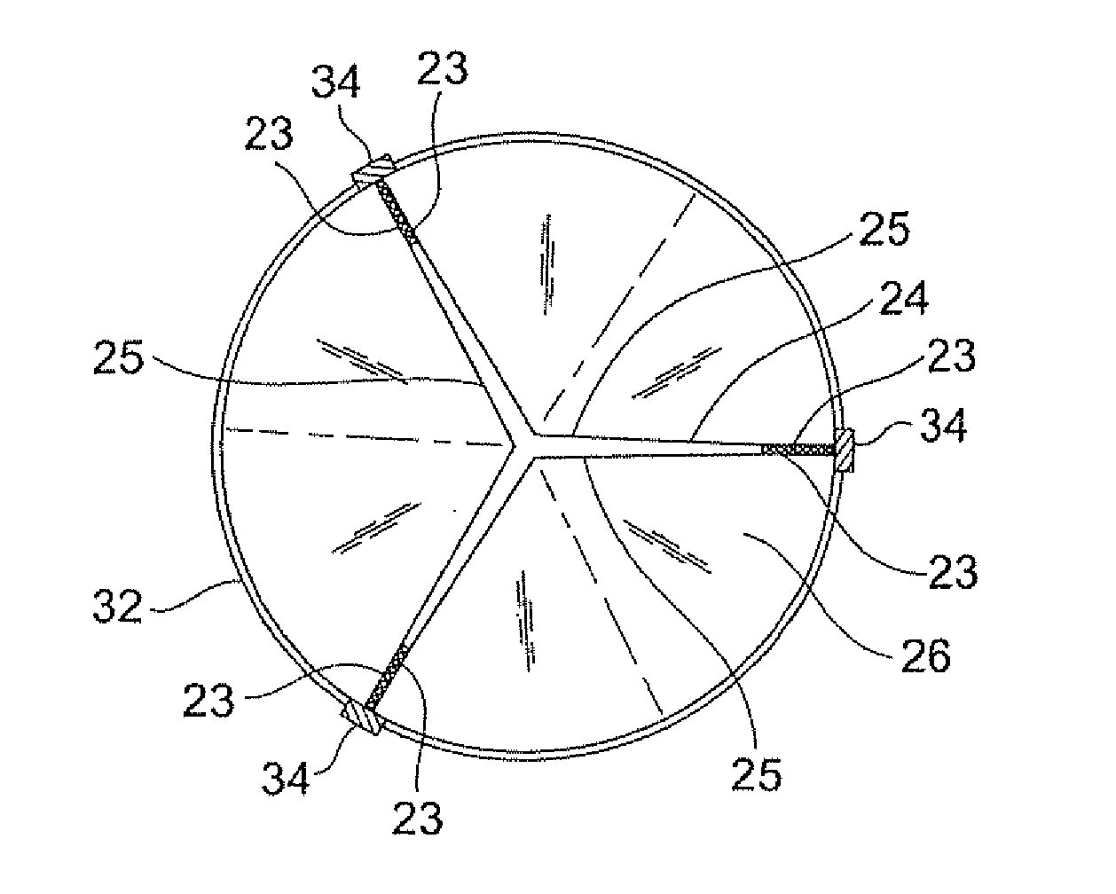
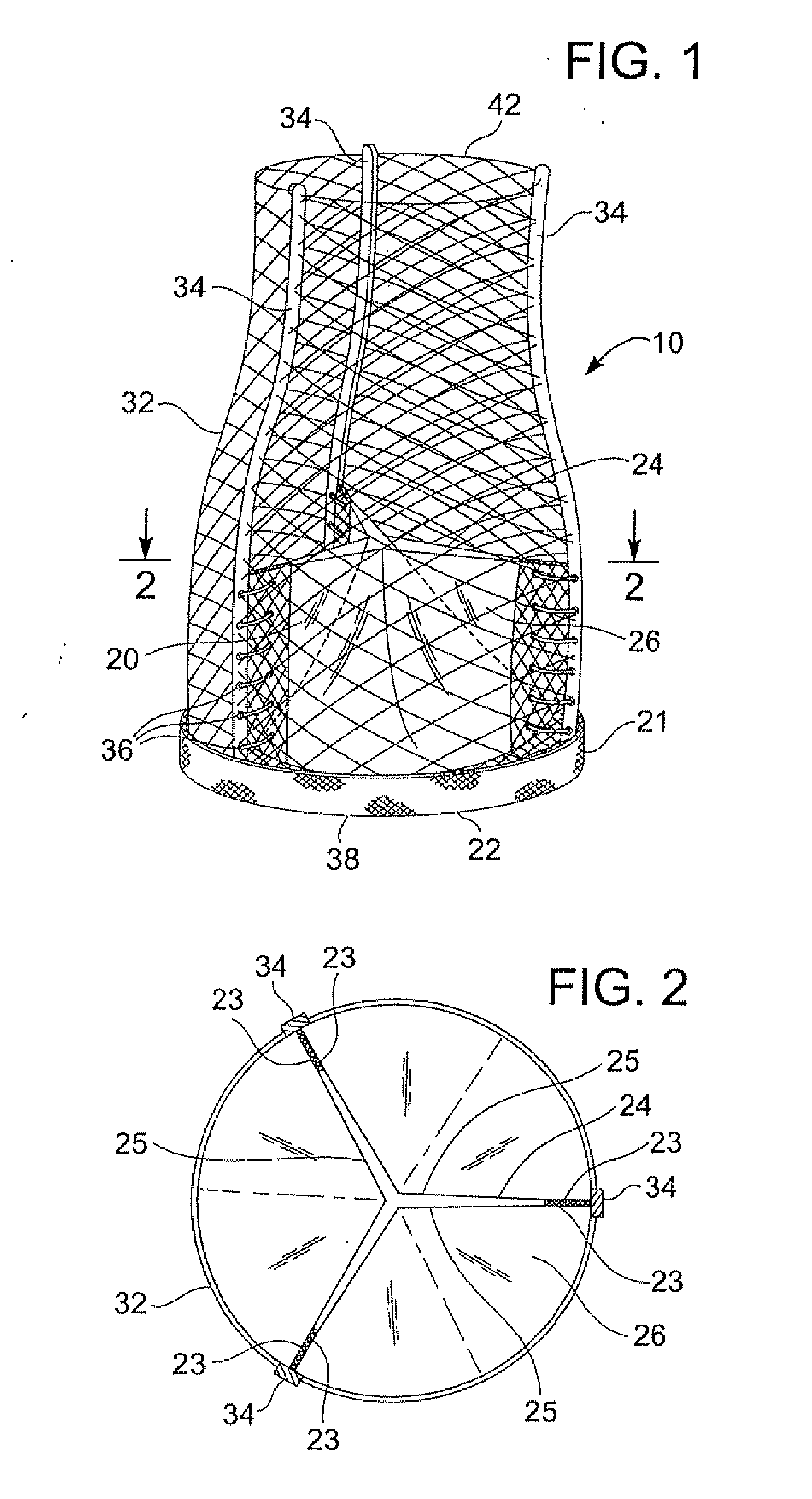
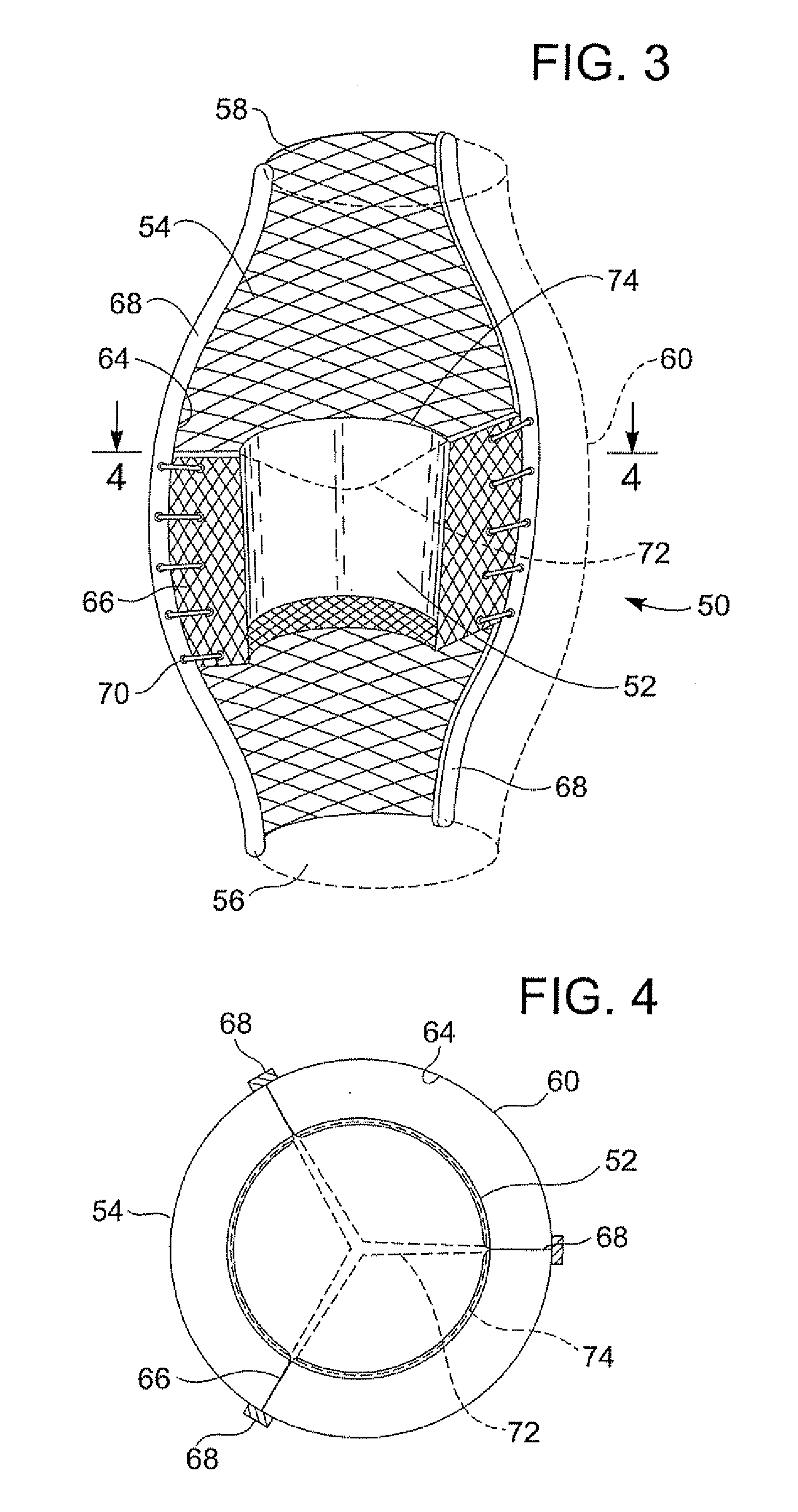
[0015]wherein when flow is allowed to pass through the valve prosthesis device from the inlet end to the outlet end, the valve assembly is kept in an open position; wherein a reverse flow is prevented as portions of the valve assembly collapse inwardly providing blockage to the reverse flow; and wherein the device is configured so that retrograde flow will be altered from laminar flow and directed towards the leaflets to effect closing.
[0019]wherein when flow is allowed to pass through the valve prosthesis device from the inlet to the outlet, the valve assembly is kept in an open position; wherein a reverse flow is prevented as the collapsible slack portions of the valve assembly collapse inwardly providing blockage to the reverse flow; and wherein the device is configured so that retrograde flow will be altered from laminar flow and directed towards the leaflets to effect closing.
[0039]Furthermore, in accordance with another preferred embodiment of the present invention, the valve assembly leaflets are longer than needed to exactly close the outlet, thus when they are in the collapsed state substantial portions of the leaflets fall on each other creating better sealing.
[0044]Furthermore, in accordance with another preferred embodiment of the present invention, the valve assembly leaflets are provided with radio-opaque material at the outlet, to help tracking the valve device operation in vivo.
[0081]Furthermore, in accordance with another preferred embodiment of the present invention, the pliant material is provided with longitudinal bars attached to the pliant material at positions assigned for attachment to the support frame, in order to prevent localized stress from forming.
[0087]Furthermore, in accordance with another preferred embodiment of the present invention, the device is further provided with spring in order to reduce wear of the pliant material.

Problems solved by technology

However, the flow characteristics are critical to effect the closing of the aortic valve, otherwise regurgitation will ensue.
Laminar flow makes the retrograde flow characteristics of valves mounted in cylindrical stents problematic as the flow along the wall is least, which is central to the closing of a valve.

Method used


Image

  • Implantable prosthetic valve with non-laminar flow
  • Implantable prosthetic valve with non-laminar flow
  • Implantable prosthetic valve with non-laminar flow

Examples


Embodiment Construction

[0105]A main aspect of the present invention is the introduction of several novel designs for an implantable prosthetic valve. Another aspect of the present invention is the disclosure of several manufacturing methods for implantable prosthetic valves in accordance with the present invention. A further aspect of the present invention is the provision of novel deployment and positioning techniques suitable for the valve of the present invention.

[0106]Basically the implantable prosthetic valve of the present invention comprises a leaflet-valve assembly, preferably tricuspid but not limited to tricuspid valves only, consisting of a conduit having an inlet end and an outlet, made of pliant material arranged so as to present collapsible walls at the outlet. The valve assembly is mounted on a support structure or frame such as a stent adapted to be positioned at a target location within the body duct and deploy the valve assembly by the use of deploying means, such as a balloon catheter o...


PUM


Abstract

A valve prosthesis device is disclosed suitable for implantation in body ducts. The device comprises a support stent comprised of a deployable construction adapted to be initially crimped in a narrow configuration suitable for catheterization through the body duct to a target location and adapted to be deployed by exerting substantially radial forces from within by means of a deployment device to a deployed state in the target location, and a valve assembly comprising a flexible conduit having an inlet end and an outlet, made of pliant material attached to the support beams providing collapsible slack portions of the conduit at the outlet. The support stent is provided with a plurality of longitudinally rigid support beams of fixed length. When flow is allowed to pass through the valve prosthesis device from the inlet to the outlet the valve assembly is kept in an open position, whereas a reverse flow is prevented as the collapsible slack portions of the valve assembly collapse inwardly providing blockage to the reverse flow. The device is configured so that retrograde flow will be altered from laminar flow and directed towards the leaflets to effect closing. The device can be deployed in a native heart valve position using a deployment catheter advanced through a body lumen such as a blood vessel, including an aorta.

Description

RELATED APPLICATIONS[0001]This application is a continuation of application Ser. No. 10 / 677,947, filed on Oct. 2, 2003 and entitled “Implantable Prosthetic Valve With Non-Laminar Flow,” the entire contents of which are hereby incorporated herein by reference.FIELD OF THE INVENTION[0002]The present invention relates to implantable prosthetic valves. More particularly, the invention relates to a valve prosthesis for cardiac implantation or for implantation in other body ducts where the prosthesis has improved flow characteristics,BACKGROUND OF THE INVENTION[0003]Several prosthetic valves are known. See, for example, U.S. Pat. No. 5,411,552 (Andersen et al.), entitled VALVE PROSTHESIS FOR IMPLANTATION IN THE BODY AND CATHETER FOR IMPLANTING SUCH VALVE PROSTHESIS, which discloses a valve prosthesis comprising a stent made from an expandable cylinder-shaped thread structure comprising several spaced apices. See, also, U.S. Pat. No. 6,168,614 (Andersen et al.), entitled VALVE PROSTHESIS F...

Claims


Application Information

Patent Timeline
Patent Type & Authority Applications(United States)
IPC IPC(8): A61F2/24A61F2/06A61F2/86
CPCA61F2/2418A61F2/2475A61F2220/0075A61F2220/0041Y10S623/904A61F2/2412A61F2210/0014A61F2250/0039A61F2/2427A61F2/2433A61F2/844
Inventor ROWE, STANTON J.
Owner EDWARDS LIFESCIENCES CORP
Learn More