Eureka AIR delivers breakthrough ideas for toughest innovation challenges, trusted by R&D personnel around the world.

Positive photoresist composition, thick film photoresist laminate, method for producing thick film resist pattern, and method for producing connecting terminal

A photoresist layer, photoresist technology, applied in photosensitive materials for photomechanical devices, use/removal methods of circuit masks, photomechanical devices, etc., can solve the problem of not being able to obtain high precision Resist patterns, etc.

Inactive Publication Date: 2008-08-20
TOKYO OHKA KOGYO CO LTD
View PDF1 Cites 5 Cited by
  • Summary
  • Abstract
  • Description
  • Claims
  • Application Information

AI Technical Summary

Problems solved by technology

[0006] However, when a photoresist layer is formed on a substrate containing copper using a chemically amplified photoresist composition, there arises a problem that high precision cannot be obtained due to an adverse effect exerted by copper. resist pattern

Method used


Image

  • Positive photoresist composition, thick film photoresist laminate, method for producing thick film resist pattern, and method for producing connecting terminal
  • Positive photoresist composition, thick film photoresist laminate, method for producing thick film resist pattern, and method for producing connecting terminal
  • Positive photoresist composition, thick film photoresist laminate, method for producing thick film resist pattern, and method for producing connecting terminal

Examples


Embodiment 1

[0256] [Synthesis Example 1]

[0257] After replacing the atmosphere in the flask equipped with a stirrer, a reflux condenser, a thermometer, and a dropping tank, propylene glycol methyl ether acetate was charged as a solvent, and stirring was started. Then, the temperature of the solvent was raised to 80°C. 2,2'-Azobisisobutyronitrile as a polymerization catalyst, 30 mol% of 2-methoxyethyl acrylate constituting units, 10 mol% of n-butyl acrylate constituting unit, 55 mol% of 2-ethyl-2-adamantyl methacrylate constituting unit represented by the following chemical formula, and 5 mol% of acrylic acid constituting unit, followed by stirring until the polymerization catalyst was dissolved. This solution was uniformly added dropwise to the flask over 3 hours, followed by polymerization at 80°C for 5 hours. The reaction product was cooled to room temperature, and then classified to obtain a resin (B-1) having a mass average molecular weight of 30,000.

Embodiment 2

[0258] [Synthesis Example 2]

[0259] In addition to using 30 mol% of 2-methoxyethyl acrylate constituting unit, 10 mol% of n-butyl acrylic acid constituting unit, 55 mol% of 2-ethyl-2-adamantyl methacrylate constituting unit represented by the following chemical formula In the same manner as in Synthesis Example 1 except for 5 mol% of acrylic acid constituting units as constituting units, a resin (B-2) having a mass average molecular weight of 100,000 was obtained.

[0260] [chemical formula 27]

[0261]

Embodiment 3

[0263]

[0264] Resin (C-1) having a mass average molecular weight of 1,500 was obtained in the same manner as in Synthesis Example 1 except that 10 mol% of hydroxystyrene constituting units and 90 mol% of styrene constituting units were used as constituting units.


PUM

PropertyMeasurementUnit
thicknessaaaaaaaaaa
thicknessaaaaaaaaaa
dispersityaaaaaaaaaa

Abstract

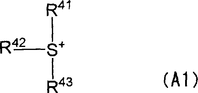
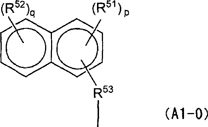
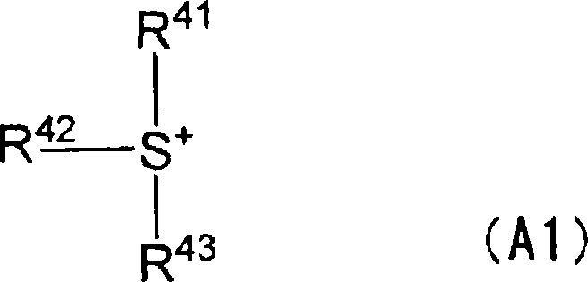
This positive photoresist composition is a positive photoresist composition for exposing to light having one or more wavelengths selected from g-rays, h-rays and i-rays, comprising: (A) a compound which generates an acid under irradiation with active rays or radiation, and (B) a resin whose solubility in an alkali is enhanced by an action of an acid, wherein the component (A) contains an onium salt (A1) having a naphthalene ring in the cation moiety.

Description

technical field [0001] The present invention relates to a positive photoresist composition, a thick film photoresist laminate, a method for preparing a thick film resist pattern and a method for preparing a connection terminal. [0002] This application claims priority from Japanese Patent Application No. 2005-099442 filed on March 30, 2005, the disclosure of which is incorporated herein by reference. Background technique [0003] With recent miniaturization of electronic devices, there is rapid progress toward higher integration of LSIs. In order to mount an LSI on an electronic device, a multipin film packaging method in which a connection terminal constituted by protruding electrodes is placed on a support such as a substrate is used. In this multi-pin packaging method, a terminal composed of a bump protruding from a support and a terminal comprising a post called a metal post protruding from the support and solder balls formed thereon are used. [0004] The bumps or me...

Claims


Application Information

Patent Timeline
Patent Type & Authority Applications(China)
IPC IPC(8): G03F7/004G03F7/039H01L21/60
CPCG03F7/0397H01L21/4853G03F7/0045H01L24/13H01L2224/1146H01L2924/01019H01L2224/13144H01L2924/01029H01L2224/13147H01L2224/1147H01L24/11H01L2924/01013H01L2924/014H05K3/0076H01L2924/01024H01L2924/01079H01L2224/13155H05K3/0079H01L2924/01033H01L2924/01005H01L2924/01006H01L2224/81192H05K3/3452H01L2924/01074H01L2924/01078H01L2924/01057H01L2924/01073H01L2224/131H01L2924/3025H01L2924/15747H01L2924/15788H01L2924/00014H01L2924/00G03F7/0047G03F7/0392
Inventor 三隅浩一鹫尾泰史先崎尊博斋藤宏二
Owner TOKYO OHKA KOGYO CO LTD
Why Eureka
Eureka Blog
Learn More