
Shaped LED lampshade emitted/extruded using in-mold transfer thin membrane

A technology of light-emitting diodes and in-mold transfer, which is applied in lampshades, semiconductor devices of light-emitting elements, and processes for producing decorative surface effects, etc. The effect of improving the yield rate, reducing the cost, and mass production

Inactive Publication Date: 2008-07-23
优利科技股份有限公司
View PDF0 Cites 5 Cited by
  • Summary
  • Abstract
  • Description
  • Claims
  • Application Information

AI Technical Summary

Problems solved by technology

[0004] The above-mentioned traditional way of manufacturing light-emitting diodes by dispensing is because the chip of the light-emitting diode is completely packaged and filled. function, and the heat dissipation is not easy, so the packaging silicone can not withstand high temperature, and it is easy to deteriorate and become brittle.
For this reason, generally known LED light-emitting diodes are only suitable for low-power use, their brightness is very limited, and their service life is not long, so they cannot break through to the ideal state of high-power, and it is difficult to develop towards lighting equipment.
[0005] Furthermore, known light-emitting diodes, because blue light-emitting diodes have the cheapest manufacturing cost, are usually implemented as light-emitting diodes that emit blue light. Traditional glue dispensing is to fill the packaging silica gel with phosphor material in the package. On the blue light diode chip, in order to obtain the effect of emitting white light, but this known structure not only cannot dissipate heat and reduce the service life, but also the labor cost and the defective rate of the product are high, and the effect is not good.

Method used


Image

  • Shaped LED lampshade emitted/extruded using in-mold transfer thin membrane
  • Shaped LED lampshade emitted/extruded using in-mold transfer thin membrane
  • Shaped LED lampshade emitted/extruded using in-mold transfer thin membrane

Examples


Embodiment Construction

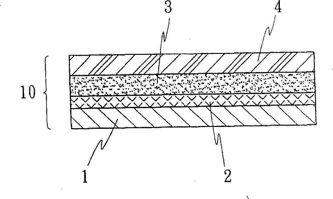
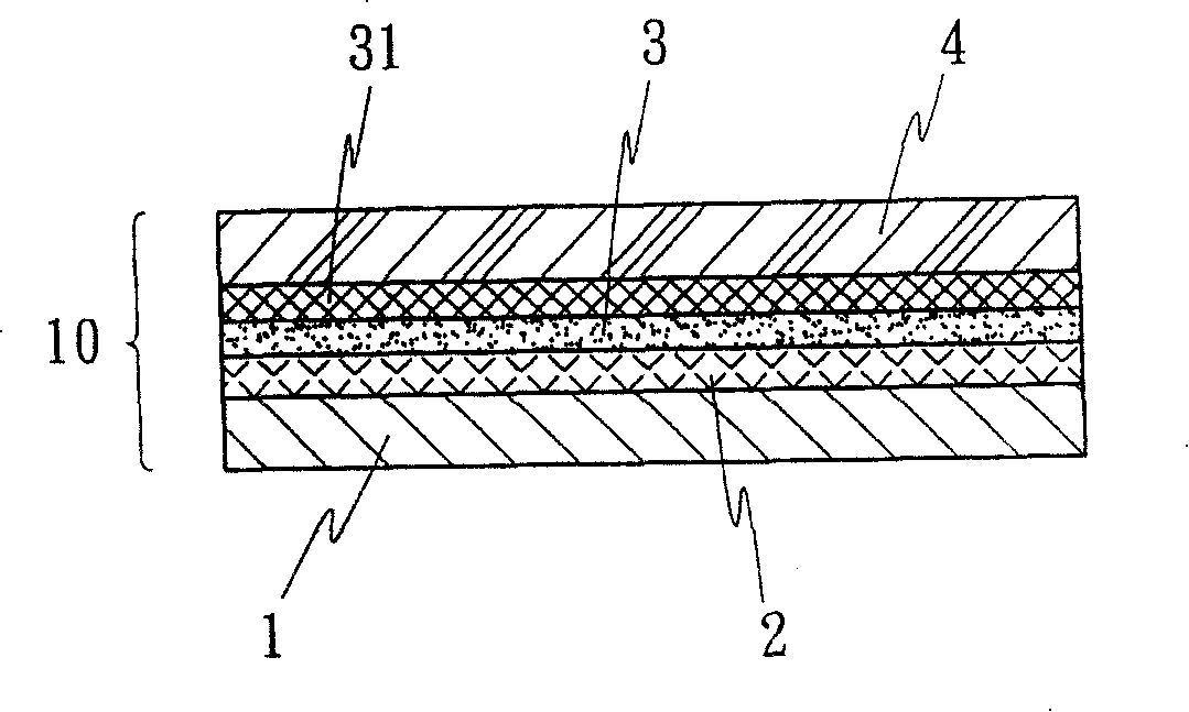
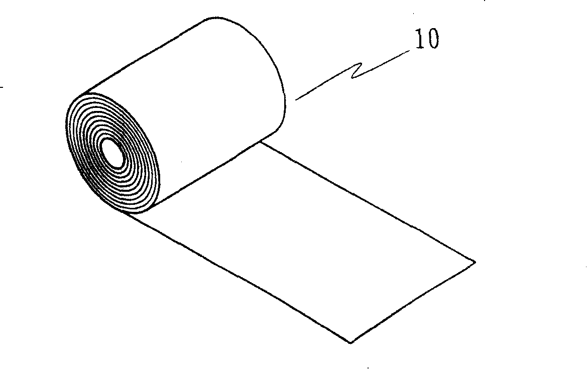
[0023] Such as figure 1 As shown, the light-emitting diode lampshade that utilizes in-mold transfer printing film injection / extrusion molding of the present invention can quickly print an in-mold transfer printing film 10 mainly through output devices such as a printing machine or a printer, so that the mold The inner transfer printing film 10 is suitable for continuous plastic injection / extrusion molding and is integrally formed and combined with the lampshade of the light-emitting diode; the printing machine equipment can be a coating machine, a screen printing machine, a gravure printing machine or a relief printing machine, etc., the printer equipment can be laser color printer or inkjet color printer, etc.; 3 and an adhesive layer 4 to form an in-mold transfer film 10, wherein:

[0024] The transparent base layer 1 can be selected as PET (polyester resin), PMMA (polymethyl methacrylate resin), PC (polycarbonate resin), ABS (polyacrylonitrile-butadiene-styrene resin) or P...


PUM


Abstract

The invention relates to a light emitting diode lamp shade which can be in injection or extrusion molding by utilizing intramode transfer printing film; the lamp shade is characterized in that: the intramode transfer printing film can be combined and molded at the light emitting diode in the method of continuous plastic injection or extrusion molding; the intramode transfer printing is that an intramode transfer printing film can be printed and completed rapidly through a printing machine or a printer or other output equipment; a parting layer, a printing layer with selective phosphor material and an adhesion layer is formed at a substrate underlayer of the intramode transfer printing film by using a printing contraposition method in sequence; thereby the light emitting diode which is composed of the lamp shade and a blue light diode chip can generate white light, or which also can be used in re-imprinting various appointed pigment ink layers on the printing layer, so that various color lights can be generated. The light emitting diode lamp shade has the advantages of lowering cost in mass production, long service life and good heat dissipation effect.

Description

technical field [0001] The invention relates to a light-emitting diode (LED element) lampshade design for injection / extrusion molding by using an in-mold transfer film. Background technique [0002] The known in-mold transfer film refers to placing the printed film in the mold cavity, and then injecting the rubber to complete the injection / extrusion molding. In-mold transfer printing is usually used in the production of key elements that require extremely high quality performance and decoration. Sexual components, such as the production of mobile phone casings, cosmetic packaging containers, buttons, auto parts or information and electrical components. [0003] Furthermore, in the known manufacturing process of light-emitting diodes (LEDs) with various colors, it is necessary to use glue dispensing to pre-package and fill the chip of the light-emitting diode with silica gel containing an appropriate amount of fluorescent powder. Set up a general encapsulation colloid, which...

Claims


Application Information

Patent Timeline
IPC IPC(8): F21V3/00F21V3/04B44C1/165F21Y101/02F21Y115/10
Inventor 许胜利
Owner 优利科技股份有限公司
Learn More