
Flexible circuit board of LED illumination array

A flexible circuit board, LED lighting technology, applied in lighting device parts, lighting devices, lighting and heating equipment and other directions, can solve the problem of high flatness, smoothness and installation requirements, the negative impact of LED light source performance, and reduce LED light source. Service life and other issues, to achieve the effect of ensuring effective thermal contact area, improving application safety and stability, and reducing indirect heat dissipation links

Inactive Publication Date: 2008-06-11
史杰
View PDF0 Cites 60 Cited by
  • Summary
  • Abstract
  • Description
  • Claims
  • Application Information

AI Technical Summary

Problems solved by technology

Conventional PCB substrates (mainly paper, fiber, and resin substrates) and ceramic substrates have large thermal resistances and are basically unable to dissipate the heat generated by LED light sources. Therefore, the use of such non-thermally conductive substrates has a great impact on the performance of LED light sources. negative impact
Metal substrates (mainly aluminum alloy substrates) have relatively good thermal conductivity, but this LED substrate is not directly exposed to the outside world. It is also necessary to install the substrate on the surface of the heat sink with screws or other structures, and radiate heat to the outside through the heat sink. Therefore, there are high requirements on the contact surface between the metal substrate and the heat sink. At the same time, there are unavoidable gaps between the LED light source and the substrate, and between the substrate and the mounting surface of the heat sink. Form a heat dissipation path of "LED light source→thermal conductive greasemetal substrate→thermal conductive grease→radiating body→outside". The heat dissipation path is multiple indirect heat dissipation, and the effect is not obvious. The flatness, smoothness and installation requirements of the surface are high, which increases the processing difficulty and processing cost; each contact surface is prone to contact gaps, resulting in a decrease in the overall effective thermal conductivity, resulting in an increase in LED junction temperature and light decay, which reduces the LED light source. service life
[0006] In addition, the above three types of rigid substrates are only suitable for the installation surface with the same shape and curvature size as the back of the substrate. They have high requirements for the use environment and are not universal. The application range is relatively narrow, which increases the application of LED lighting in light distribution. other restrictions

Method used


Image

  • Flexible circuit board of LED illumination array
  • Flexible circuit board of LED illumination array
  • Flexible circuit board of LED illumination array

Examples


Embodiment 1

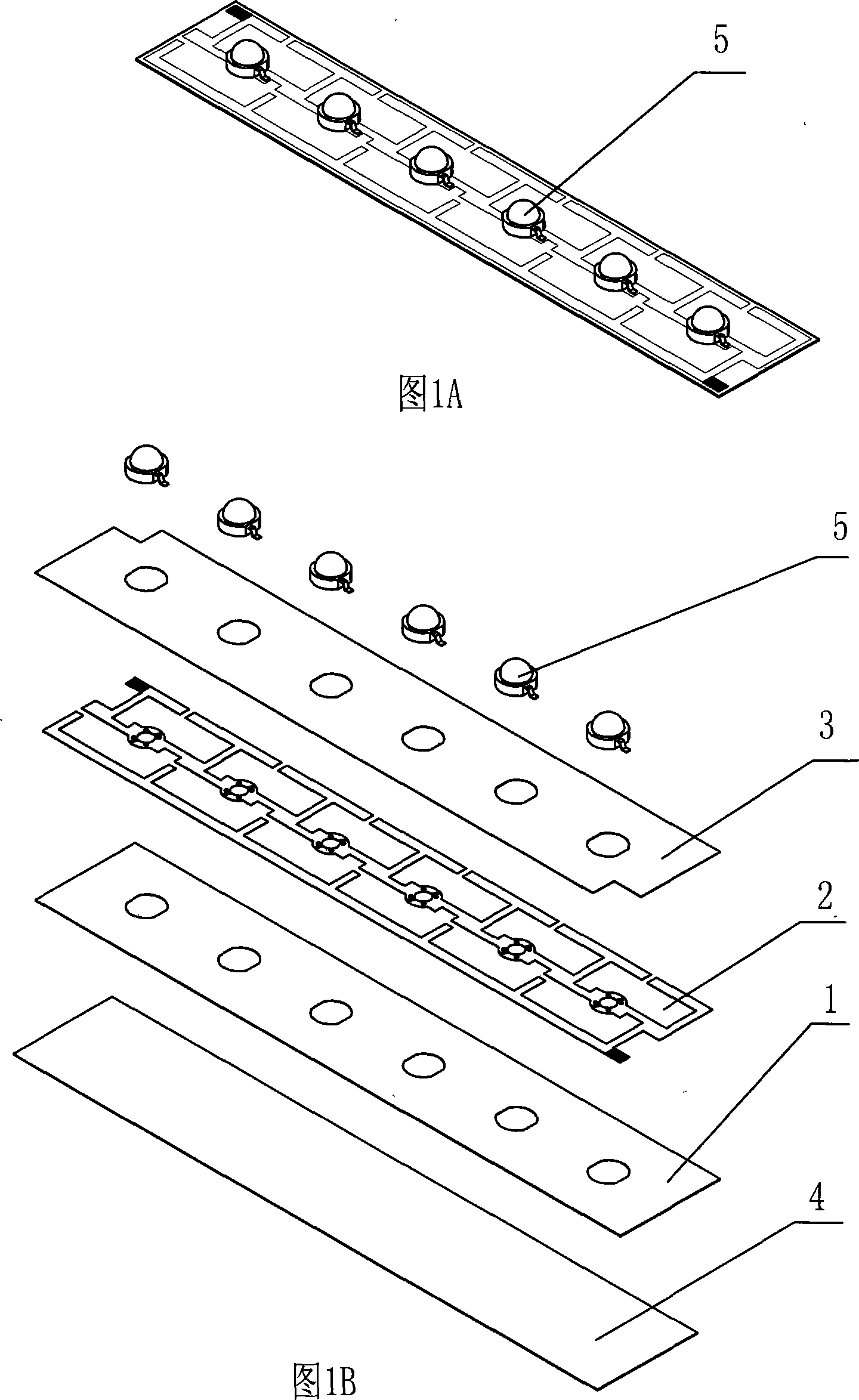
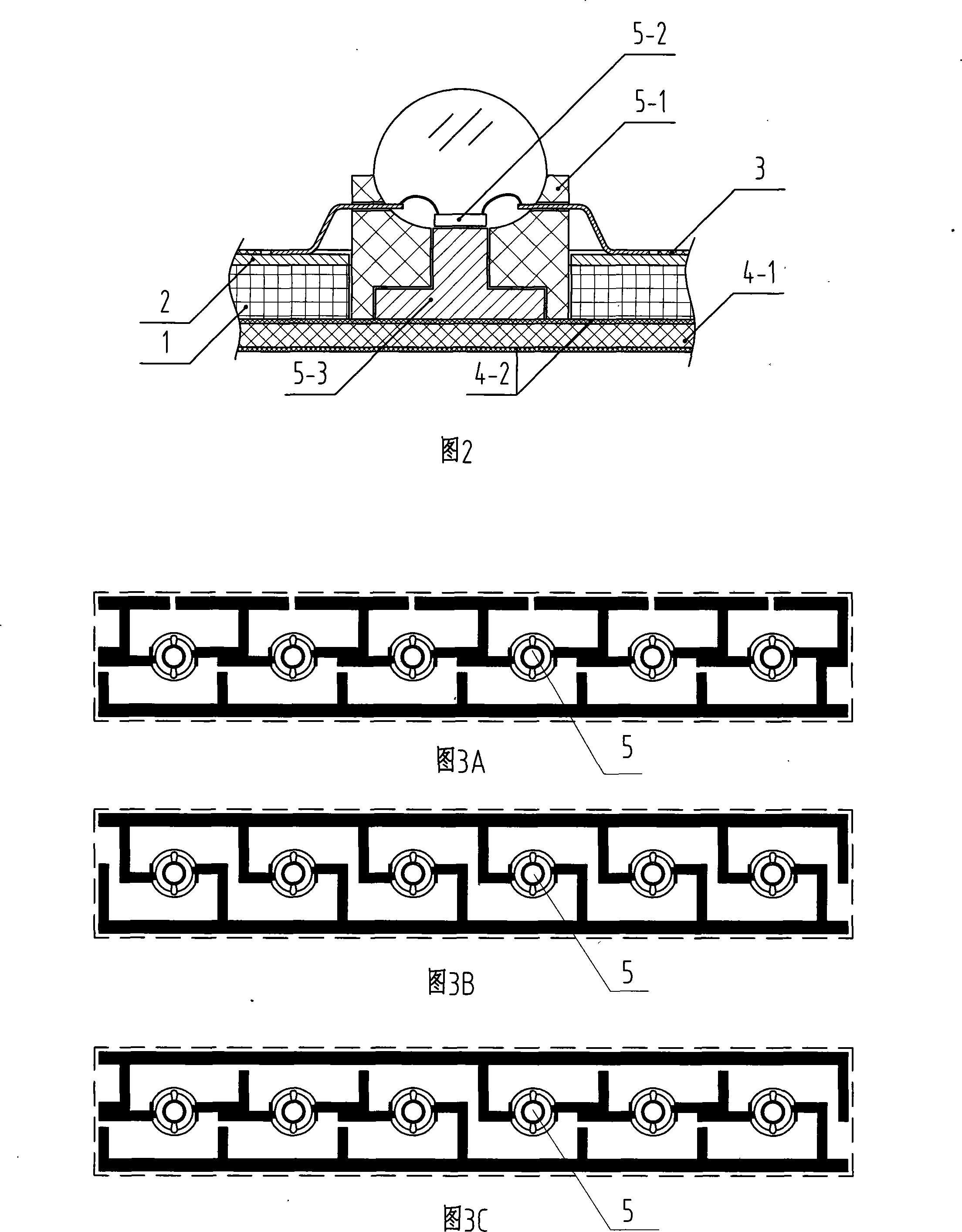
[0043] As shown in FIG. 5 , the LED lighting array flexible circuit board module is composed of a flexible substrate 1 , a connecting circuit 2 , an insulating coating layer 3 , a heat-conducting rubber pad 4 and an LED light source 5 . The flexible substrate 1 is bonded to the surface of the thermally conductive rubber pad 4 by the temperature-resistant strong adhesive layer 4-2 on one side of the thermally conductive rubber pad 4 , the connecting circuit 2 is placed on the surface of the flexible substrate 1 by thermocompression, and the transparent insulating coating layer 3 Cover the surface of the flexible substrate 1 and the connecting circuit 2 by spraying, and leave two pads at one end of the LED lighting array flexible circuit board module near the side. The pads are only electrically connected to the connecting circuit 2 without changing the original Wiring structure, pad surface gold-plated.

[0044] A single LED lighting array flexible circuit board module is insta...

Embodiment 2

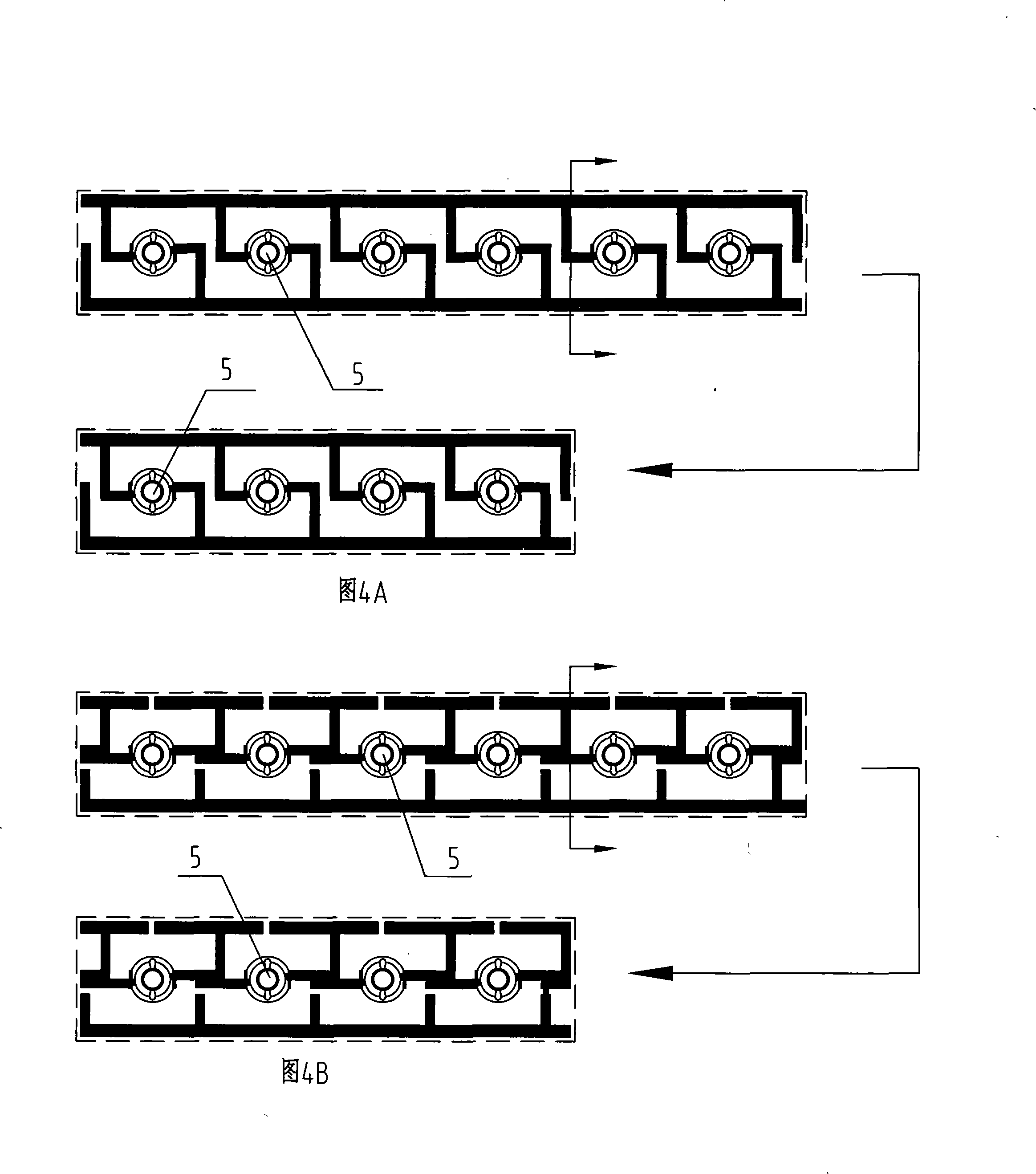
[0048] As shown in FIG. 6 , each LED lighting array flexible circuit board module is composed of a flexible substrate 1 , a connecting circuit 2 , an insulating coating layer 3 , a heat-conducting rubber pad 4 and an LED light source 5 . The flexible substrate 1 is bonded to the surface of the thermally conductive rubber pad 4 by the temperature-resistant strong adhesive layer 4-2 on one side of the thermally conductive rubber pad 4 , the connecting circuit 2 is laid on the surface of the flexible substrate 1 by means of adhesive sheets, and the transparent insulating coating layer 3 Also cover the surface of the flexible substrate 1 and the connection circuit 2 with an adhesive sheet, and leave two pads at one end of the LED lighting array flexible circuit board module near the side. The pads are only electrically connected to the connection circuit 2 and are not connected. The original wiring structure is changed, and the surface of the pad is tinned, silver-plated, or gold-p...


PUM


Abstract

The invention discloses a flexible circuit board convenient for efficient heat dissipation and mainly used in a high-power LED illumination array, belonging to the semiconductor illumination technical field. The flexible circuit board of an LED illumination array is characterized in that: the circuit board is provided with a flexible substrate, a connection circuit, an insulating film-covered layer, a heat-conducting rubber pad and an LED light source; the connection circuit is arranged on the surface of the flexible substrate; the surfaces of the flexible substrate and the connection circuit are covered with the insulating film-covered layer to form a circuit board module; the LED light source is packaged inside the circuit board module in an array mode; the bottom surface of the flexible substrate is adhered to the surface of the heat-conducting rubber pad. Therefore, the entire flexible circuit board module has certain elasticity and flexibility and can adapt to bending, twisting and crimp deformation of certain strength; moreover, the invention can also be arranged on non-flat surfaces not more than a certain curvature such as a cylindrical surface or a spherical surface. The invention has wider application scope, better heat dissipation performance, less production cost, convenient installation and substantially increased production efficiency.

Description

technical field [0001] The invention discloses a flexible circuit board which is convenient for high-efficiency heat dissipation and is mainly used in high-power LED lighting arrays, and belongs to the technical field of semiconductor lighting. Background technique [0002] LED (light-emitting diode) technology began in the late 1960s. After half a century of rapid development, LED light sources, especially high-power and bright LED light sources, are known for their high luminous efficiency, small size, long service life, and environmental protection and energy saving. And many other advantages, it occupies an important position in the lighting source, and it is still developing rapidly. [0003] In the original LED lighting products, the LED light source was directly packaged inside the lamp body. Because the lamp body material is mostly conductive metal, the insulation protection of the circuit must be considered when connecting the circuit, which is time-consuming and la...

Claims


Application Information

Patent Timeline
Patent Type & Authority Applications(China)
IPC IPC(8): H05K1/18H05K1/02H05K7/20H05B37/00F21V23/00H01L33/64
CPCH01L2924/0002H05K3/0061H05K1/182H01L33/642H05K1/021H05K2201/10106H01L2224/48091H01L2224/73265H01L2224/48247
Inventor 史杰
Owner 史杰
Learn More