Combination cooling method and device of microchannel single convective flow and capillary microgroove phase conversion heat
A technology of phase conversion heat and cooling method, which is applied in the direction of instrument cooling, cooling/ventilation/heating modification, and instrument, etc. It can solve the problems of large total heat dissipation capacity, high heat flow density, small heat dissipation area, etc., and achieve good cooling Effect of heat dissipation, high strength, and high convective heat transfer coefficient
- Summary
- Abstract
- Description
- Claims
- Application Information
AI Technical Summary
Problems solved by technology
Method used
Image
Examples
Embodiment 1
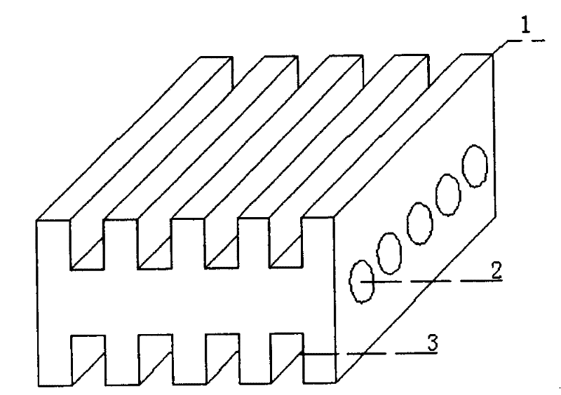
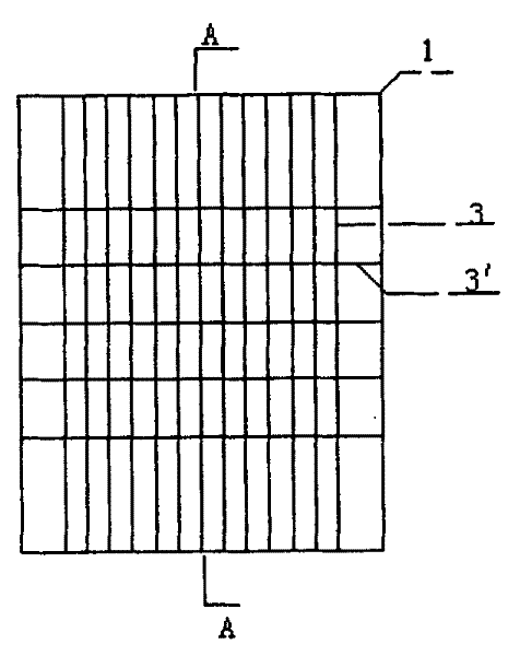
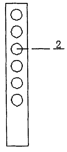
[0025] Example 1: see figure 1 , many circular microchannels 2 are arranged inside the metal plate or other heat-conducting materials 1 to form a microchannel group, and many rectangular capillary microgrooves 3 are arranged on the outer surface to form a capillary microgroove group, which has microchannels and capillary microgrooves The heat exchange structure is called a heat sink. See figure 1 , image 3 , the microchannels 2 are densely arranged laterally inside the thermally conductive material 1, see figure 1 , figure 2 , the capillary micro-grooves 3 are vertically densely arranged. The diameter of the microchannel 2 is in the range of 0.05-1mm, the distance between the microchannels is in the range of 0.05-5mm, the length of each microchannel is in the range of 5-50mm, and the cross-section of the microchannel is circular, and the capillary microgroove 3 The channel is a rectangular micro channel, its width and channel depth are in the range of 0.05-2mm, and the ...
Embodiment 2
[0027] Example 2: see figure 2 In this embodiment, the plurality of capillary microgrooves 3 of the heat sink are densely arranged vertically, and the capillary microgrooves 3 arranged longitudinally are densely arranged with a plurality of transverse capillary microchannels 3 ′. The capillary microchannels 3' arranged horizontally can ensure the capillary driving force of the liquid working medium flowing along the longitudinal capillary microchannels 3 under ultra-high heat load, so that the liquid working medium evaporated in the heated area can be replenished in time, thereby improving the cooling efficiency. In this embodiment, the groove width of the capillary micro-channel 3 is 0.2mm, the groove depth is 0.5mm, and the groove spacing is 0.2mm, and the groove width of the transverse capillary micro-channel 3' is 0.4mm, the groove depth is 0.8mm, and the groove spacing is 5mm.
Embodiment 3
[0028] Embodiment 3: see Figure 4 , a plurality of capillary grooves 4 of the heat sink in this embodiment are vertically densely arranged, and its cross section is trapezoidal. .
PUM
 Abstract
Description
Claims
Application Information
 - R&D
- Intellectual Property
- Life Sciences
- Materials
- Tech Scout
- Unparalleled Data Quality
- Higher Quality Content
- 60% Fewer Hallucinations
Browse by: Latest US Patents, China's latest patents, Technical Efficacy Thesaurus, Application Domain, Technology Topic, Popular Technical Reports.
© 2025 PatSnap. All rights reserved.Legal|Privacy policy|Modern Slavery Act Transparency Statement|Sitemap|About US| Contact US: help@patsnap.com


