
Water cooling system for dry transformer

A dry-type transformer and water-cooling system technology, applied in the direction of transformer/inductor cooling, etc., can solve the problem that the air-cooled device cannot reach customers.

Inactive Publication Date: 2008-06-18
CHINESE ELECTRICAL EQUIP GRP CO LTD
View PDF0 Cites 12 Cited by
  • Summary
  • Abstract
  • Description
  • Claims
  • Application Information

AI Technical Summary

Problems solved by technology

The special occasions of marine transformers require that the operating temperature of the transformer can only reach about 45°C, while the operating temperature of the transformer with the original air-cooled device can reach 80-120°C, so the original air-cooled device can no longer meet the needs of customers

Method used


Image

  • Water cooling system for dry transformer

Examples


Embodiment Construction

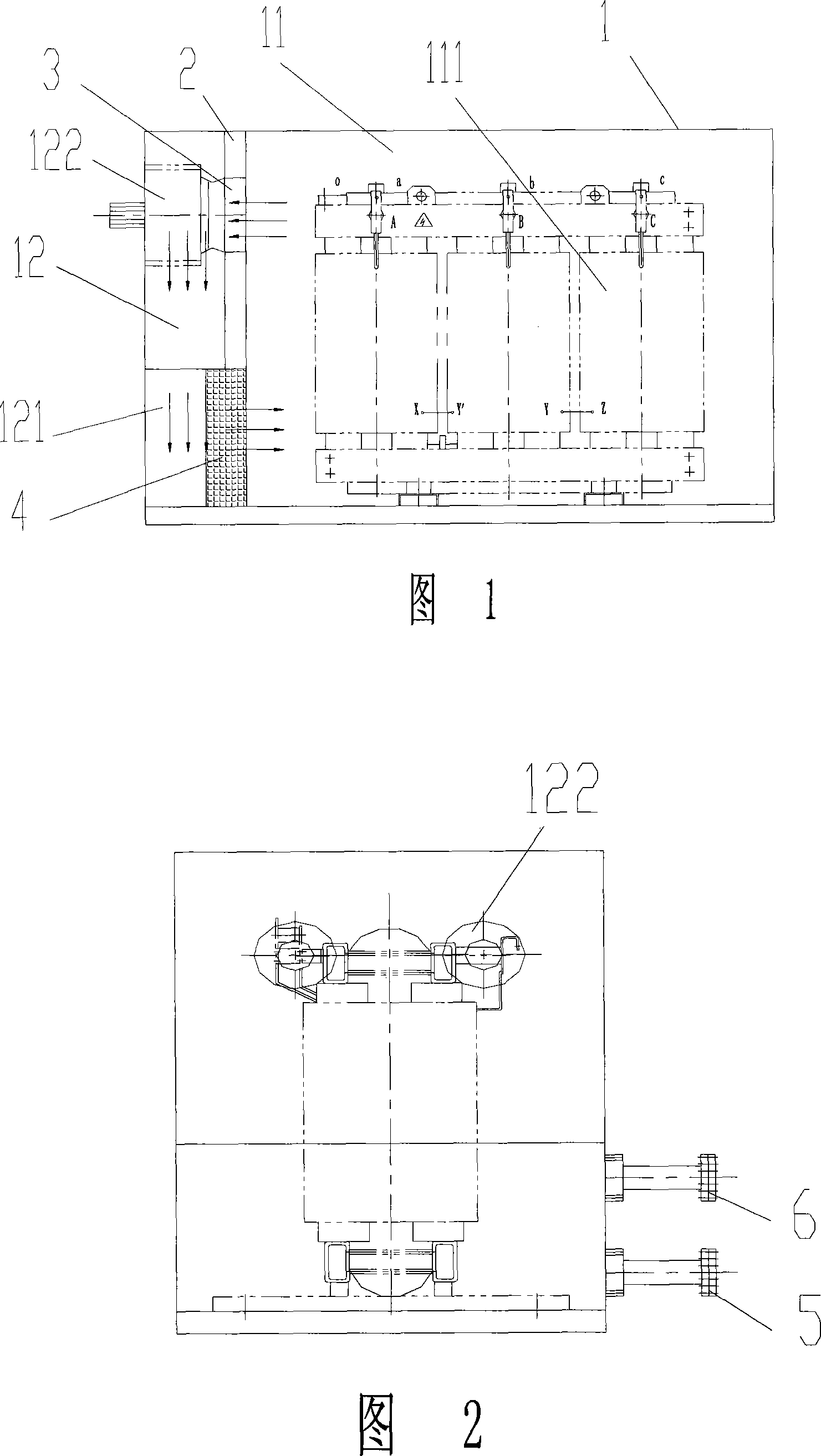
[0008] As shown in the figure, the present invention includes a housing 1, a baffle plate 2 is arranged in the housing 1, and the baffle plate 2 divides the housing 1 into a transformer room 11 and a water cooling system room 12. The transformer room 11 is provided with a transformer 111, and the water cooling system A condenser 121 and a centrifugal fan 122 are arranged in the chamber 12; an air inlet 3 is arranged on the baffle 2 connected to one end of the centrifugal fan 122, and an air outlet 4 is arranged on the baffle 2 connected to one end of the condenser 121; The water inlet pump 5 and the water outlet pump 6 are provided, the water inlet pump 5 is connected with the water inlet of the condenser 121 , and the water outlet pump 6 is connected with the water outlet of the condenser 121 .

[0009] The present invention divides the closed shell 1 into two parts, the right side is a transformer room 11, in which a transformer 111 is placed; the left side is a water cooling...


PUM


Abstract

The invention discloses a water cooling device used for a dry transformer, in particular to a water cooling device used for the dry transformer and relating to the technique field of transformer accessories. The invention comprises a casing, a baffle is arranged in the casing; the baffle divides the casing into a transformer room and a water-cooling system room. A transformer is arranged in the transformer room, and a condenser and a centrifugal fan are arranged in the water-cooling room. An air intake is arranged on the baffle which is connected with one end of the centrifugal fan and an air outlet is arranged on the baffle which is connected with one end of the condenser. A water feeding pump and a water draining pump are respectively arranged on the casing and are respectively connected with a water intake and a water outlet of the condenser. The invention realizes the aim of decreasing temperature well and stabilizing work state.

Description

technical field [0001] The invention relates to the technical field of transformer accessories, in particular to a water-cooled cooling device for dry-type transformers. Background technique [0002] The transformer will generate heat during operation. If the heat cannot be dissipated in time, it will affect the stable operation of the transformer. The conventional air-cooling device of the existing dry-type transformer is to start the axial flow fan fixed on the channel steel of the foot, and the cold air will discharge the heat during the operation of the transformer to the outside of the transformer shell through the heat dissipation air passage of the transformer coil, so as to achieve cooling. Effect. The structure is compact and safe, which can fully guarantee the reliable operation of the product. With the comprehensive advancement of my country's modernization process, users have higher and higher requirements for products, especially for transformers used in some ...

Claims


Application Information

Patent Timeline
IPC IPC(8): H01F27/16
Inventor 刘群
Owner CHINESE ELECTRICAL EQUIP GRP CO LTD
Learn More