
Layered metal composite material manufacturing technology and equipment

A manufacturing process and composite material technology, applied in the field of metal composite material production technology, can solve the problems of inability to manufacture forged core material composite products, low cleanliness and production efficiency of outer layer materials, complex production equipment production process, etc. The effect of controlling interface quality, product quality is easy to control, and production process is easy to operate

Active Publication Date: 2010-05-12
丁刚 +1
View PDF5 Cites 0 Cited by
  • Summary
  • Abstract
  • Description
  • Claims
  • Application Information

AI Technical Summary

Problems solved by technology

However, this process has complex production processes and difficult process control. When producing high-alloy outer layer composite materials, segregation is easy to occur, making the structure and composition uneven, and it is impossible to manufacture composite products of forged core materials.
[0004] In Chapter 4 (Manufacturing Layered Composite Materials) of Chapter 13 of the book "Chinese Material Engineering Compendium" Volume 5 (Chemical Industry Press, 2006, the first edition) introduces the continuous cladding layer developed by Japan. The CPC production process of manufacturing composite rolls by casting composite method. This process is to pour the outer metal liquid that needs to be composited into a water-cooled crystallizer with a mandrel material installed in its center. The mandrel material is heated by induction installed on its upper part. Preheating of the machine, so that the compounding of the two materials can be realized, and the interface between the two materials can be metallurgically bonded. The compounded roll is continuously drawn out from the water-cooled crystallizer through the ingot drawing equipment, so that the production can be continued. , until the casting of the composite roll is completed. Although this process overcomes the shortcomings of the conventional insert-casting composite process that it cannot manufacture bimetallic composite products with a composite ratio of less than 8.0 and the centrifugal casting process. However, due to the complex production equipment and production process of the CPC method , the production cost is high, the cleanliness and production efficiency of the outer layer material are low, and the scope of promotion and use has been very small. The book also introduces a composite method of electroslag coating casting developed in Ukraine. This process is to use the mandrel material Installed in the center of the conductive crystallizer, the conductive water-cooled crystallizer replaces the non-consumable electrode to heat the electroslag, so that the liquid slag is kept at a high temperature, and the outer metal liquid to be compounded is poured into the conductive water-cooled at a certain speed and method. In the crystallizer, the outer metal liquid is refined by electroslag while being fused with the surface of the roll core material that has been preheated by electroslag, and is solidified by the cooling of the water-cooled mold to form a composite layer. The high-temperature liquid electroslag also It is used to heat the mandrel, clean the surface and isolate the contact between the poured metal liquid and the air, so as to protect the metal liquid. Compared with the CPC process, although the equipment is simple and the product quality is good, it is still There are disadvantages such as low production efficiency, complex structure of conductive crystallizer, high technical difficulty, and high technical difficulty in equipment control.

Method used


Image

  • Layered metal composite material manufacturing technology and equipment
  • Layered metal composite material manufacturing technology and equipment
  • Layered metal composite material manufacturing technology and equipment

Examples


Embodiment 1

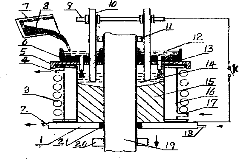
[0018] Embodiment 1: In Fig. 1, this equipment has a workbench, a hole is arranged on the workbench, a lifting device 20 is installed below the workbench, water-cooled crystallizer 16 and electrode holder 9 are installed above the workbench. The outside of the water-cooled crystallizer 16 is equipped with an induction heater 3, an insulation cover 5 and a pouring funnel 6 are installed above the water-cooled crystallizer 16, a bottom water tank 1 is installed below the water-cooled crystallizer 16, and a bottom water tank 1 is installed under the water-cooled crystallizer 16. The water inlet pipe 17 and the water outlet pipe 4 are respectively connected with the upper part, and the water inlet pipe 18 and the water outlet pipe 2 are respectively connected with the bottom and the upper part of the bottom water tank 1. The metal mandrel 19 passes through the center hole bushing 21 of the bottom tank 1 through the center of the water-cooled crystallizer 16 and is fixed on the lift...

Embodiment 2

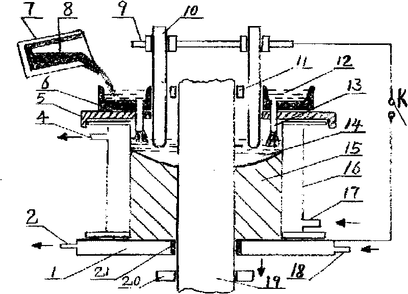
[0020]Embodiment 2: In Fig. 2, the difference from Fig. 1 is that no induction heater 3 is installed outside the crystallizer 16. After the work starts, the power supply K is directly started to melt the electroslag 14, and the metal core is passed through the liquid electroslag 14. Rod 19 is heated directly. Other processes and equipment are the same as in Embodiment 1, omitted.

Embodiment 3

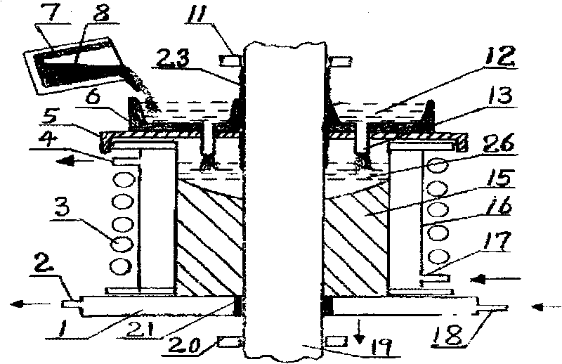
[0021] Embodiment 3: In Fig. 3, the difference from Fig. 1 is that there are no electrode holders 9, electrodes 10 and power supply K equipment on the top of the crystallizer 16. After the work starts, the metal mandrel 19 that needs to be composited will be surface treated Finally, the surface is coated with an anti-oxidation coating 23 containing a low-melting-point molten salt such as borax or an oxide, and after being dried, it is installed in the center of the water-cooled crystallizer 16 and passes through the center hole bushing 21 of the bottom water tank 1 Fixed on the lifting device 20, the ultrasonic vibrator 11 is installed on the top of the metal mandrel 19. After smelting the required composite metal, put it into the metal casting ladle 7, put the anti-oxidation slag material 26 with low melting point into the water-cooled crystallizer 16, open the inlet and outlet pipes 17 and 4 of the water-cooled crystallizer 16 and the inlet and outlet of the bottom water tank...


PUM


Abstract

The present invention relates to a technique for producing laminated and composite metal material, belonging to manufactural technique of composite metal material. The present technique for producinglaminated and composite metal material is characterized by simple process, high production efficiency, low production cost, simple facility and small investment. In the method, metal liquid is directcast into a crystallizer with an induction heater on the external part. The metal liquid is refined by electroslag in the crystallizer and is simultaneously combined with metal mandril installed in the crystallizer to achieve the aim of metallurgical combination. The interface of compound layer can be easily controlled with no composition segregation in product. With highly structural density, high product quality and wide selectivity about both the madril and the material of the compound layer, the prevent invention is free from limitation of facility and technique to achieve producing laminated and multilayer composite product in large volume by small equipment.

Description

technical field [0001] The invention relates to a metal composite material production process, in particular to a layered composite material production process and equipment. Background technique [0002] Layered metal composite material is a new material that forms a whole by different materials through casting, rolling, extrusion, welding, bonding and impregnation, so that different parts of the material have different properties. Requirements. [0003] The document "Special Casting and Nonferrous Alloys" magazine (No. 2, 2001, pages 17-19) reported "Research on the interface of high-speed steel / structural steel bimetallic composite materials", and disclosed a bimetallic composite material manufacturing process in the report , the commonly used process is the sand casting method, which is to put the required core material into the sand mold, and pour the required composite liquid metal into the sand mold. When the liquid metal fills the mold cavity, it also The core mate...

Claims


Application Information

Patent Timeline
Patent Type & Authority Patents(China)
IPC IPC(8): B22D19/08
Inventor 丁刚丁家伟
Owner 丁刚
Learn More