Method for optimizing radio-frequency power amplifier and radio-frequency power amplifier system

A radio frequency power and amplifier technology, applied in the field of methods and radio frequency power amplifier systems, can solve problems affecting the performance of power amplifiers, and achieve the effect of dynamic optimization

Active Publication Date: 2009-02-11
HUAWEI TECH CO LTD
View PDF1 Cites 0 Cited by
  • Summary
  • Abstract
  • Description
  • Claims
  • Application Information

AI Technical Summary

Problems solved by technology

The method of manual debugging is obviously affected by environmental and human factors. For example, the temperature difference between the temperature during debugging and the ambient temperature of the power amplifier field application will have some impact on the parameters that were debugged at that time, thus affecting the performance of the power amplifier. , and this method is only suitable for occasions with narrow bandwidth and low requirements; if the method of setting a fixed pilot frequency is used, the complicated debugging work will be saved, but this method is an open-loop control method, that is, when the actual When the working frequency band changes, the fixed pilot cannot have any adjustment effect on the working performance of the power amplifier.

Method used


Image

  • Method for optimizing radio-frequency power amplifier and radio-frequency power amplifier system
  • Method for optimizing radio-frequency power amplifier and radio-frequency power amplifier system
  • Method for optimizing radio-frequency power amplifier and radio-frequency power amplifier system

Examples


Embodiment 1

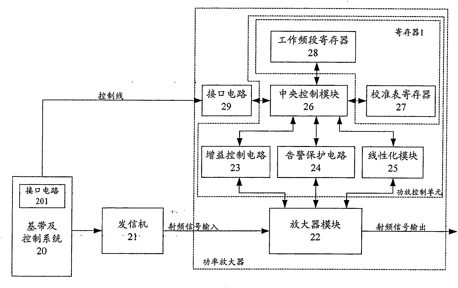
[0063] figure 2 It is a schematic diagram of the system of the preferred embodiment 1 of the present invention. The preferred embodiment 1 includes the existing central control module 26, gain control circuit 23, alarm protection circuit 24, linearization module 25 and amplifier module 22 in the power amplifier, wherein The gain control circuit 23, the alarm protection circuit 24, the linearization module 25 and the central control module 26 can be called a power amplifier control unit. The system also includes an interface circuit 29, and a register 1 is also included in the power amplifier control unit. The module 20 also includes an interface circuit 201 . In this embodiment, the register 1 is composed of a working frequency band register 28 and a calibration table register 27 .

[0064] Wherein, in the calibration table register 27, the parameters corresponding to the optimization of the power amplifier on each small frequency band divided in the specified frequency of t...

Embodiment 2

[0077] see figure 2 The system schematic diagram of the preferred embodiment 1 of the present invention, and the preferred embodiment 2 is in figure 2 On the basis of the preferred embodiment 1 shown, the calibration table register 27 can be removed, that is, in this embodiment, the register 1 is composed of the working frequency band register 28, and the working frequency band register is also used to store the information of the actual working frequency point.

[0078] Combine below Figure 4 The specific working steps of the second preferred embodiment of the present invention are described. It is assumed that both the interface circuit 29 and the interface circuit 201 adopt the serial port communication mode, and the two interface circuits are connected by a control line.

[0079] combine Figure 4 The flow chart of the second preferred embodiment of the present invention, this embodiment sets the pilot frequency according to the actual working frequency point informa...


PUM


Abstract

This invention discloses a method for optimizing RF power amplifier including: a power amplifier receives an actual working frequency point to adjust the performance parameters of the power amplifier. This invention discloses a RF power amplifier system, which gets information of actual working frequency points by a baseband then to be transmitted to a power amplifying control unit of the power amplifier via an interface circuit, in which, the power amplifying control unit determines the most suitable working performance parameter based on the point information to optimize the input and output property of the power amplifier.

Description

technical field [0001] The invention relates to a radio frequency power amplifier technology, in particular to a method for optimizing a radio frequency power amplifier and a radio frequency power amplifier system. Background technique [0002] In this paper, the radio frequency power amplifier is referred to simply as the power amplifier. [0003] In the wireless base station system, the power amplifier is a device used to amplify the small signal of the transmitter to a certain power. The function of the power amplifier is to amplify the radio frequency signal from the transmitter as much as possible without distortion. Hereinafter, the power amplifier is simply referred to as the power amplifier. [0004] figure 1 It is a schematic diagram of the application of the power amplifier in the prior art in the wireless base station system, wherein the power amplifier is mainly composed of five modules: an amplifier module 12, a gain control circuit 13, an alarm protection ci...

Claims


Application Information

Patent Timeline
Patent Type & Authority Patents(China)
IPC IPC(8): H03F1/32H03F3/20H03G3/20
Inventor 殷为民苏永革
Owner HUAWEI TECH CO LTD
Why Eureka
Try Eureka