
Die assembly with cooled die land

a die assembly and die land technology, applied in the direction of insulating conductors/cables, cables, insulated conductors, etc., can solve the problems of affecting increasing the cost, time and complexity of the coating manufacturing process, and adding such materials can have an adverse effect on one or more other properties of the coating, so as to reduce the waiting time for the migration of organic or inorganic additives to the coating surface, excellent matte surface characteristics, and the effect o

Active Publication Date: 2018-05-22
DOW GLOBAL TECH LLC
View PDF22 Cites 0 Cited by
  • Summary
  • Abstract
  • Description
  • Claims
  • Application Information

AI Technical Summary

Benefits of technology

This patent describes a new design for a die assembly that reduces surface gloss in wire and cable coatings without using organic or inorganic ingredients. The design can be used with different polymer formulations and temperatures. The invention has two main benefits: it creates a matte surface and reduces the waiting time for a cooling medium to take effect.

Problems solved by technology

The addition of organic or inorganic additives to the coating formulation, e.g., aluminum trihydrate with a particle size in excess of 5 microns, can reduce the gloss of the wire and cable coating, but this adds expense, time and complexity to the coating manufacturing process.
Moreover, the additions of such materials can have an adverse impact on one or more of the other properties of the coating, e.g., flexibility, tensile measures and the like.

Method used


Image

  • Die assembly with cooled die land
  • Die assembly with cooled die land
  • Die assembly with cooled die land

Examples


specific embodiments

[0042]One cable formulation was prepared using TPU resin with flame retardant (aluminum trihydrate (ATH, 40-50%) and an antioxidant. The formulation is reported in Table 1.

[0043]

TABLE 1Cable Coating FormulationComponentSupplierA 1687 GY EXP1TPU (EstaneLubrizol32.6458219)MG1 MBNHH2.00(K7JK9)BDP (FP600)CCP13.51NovolacDow1.69(DEN431)ATH (H-42M)Showa39.33TiO2 (R103)DuPont9.22 168BASF0.091010BASF0.52 866BASF1.00Sum100.00

[0044]The inventive composition was processed along with a commercially available product as a comparative example. The processing conditions are reported in Table 2:

[0045]

TABLE 2Cable Coating ConditionsLine SpeedDie CoolingAppearance of CoatingSample 130 m / minNo air coolingVery glossySample 272 m / minAir cooling; A little glossy~200 l / h, 2 barSample 343 m / minAir cooling: Matte~200 l / h, 2 bar

[0046]Scanning Electron Micrograph (SEM) micrographs of the sample surfaces are shown in FIGS. 4-6. The SEM images demonstrate the improved surface roughness of Sample 3 relative to th...


PUM

PropertyMeasurementUnit
particle sizeaaaaaaaaaa
temperatureaaaaaaaaaa
glossaaaaaaaaaa

Abstract

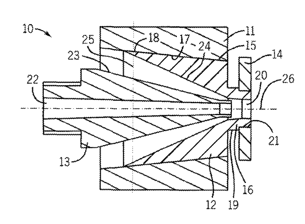
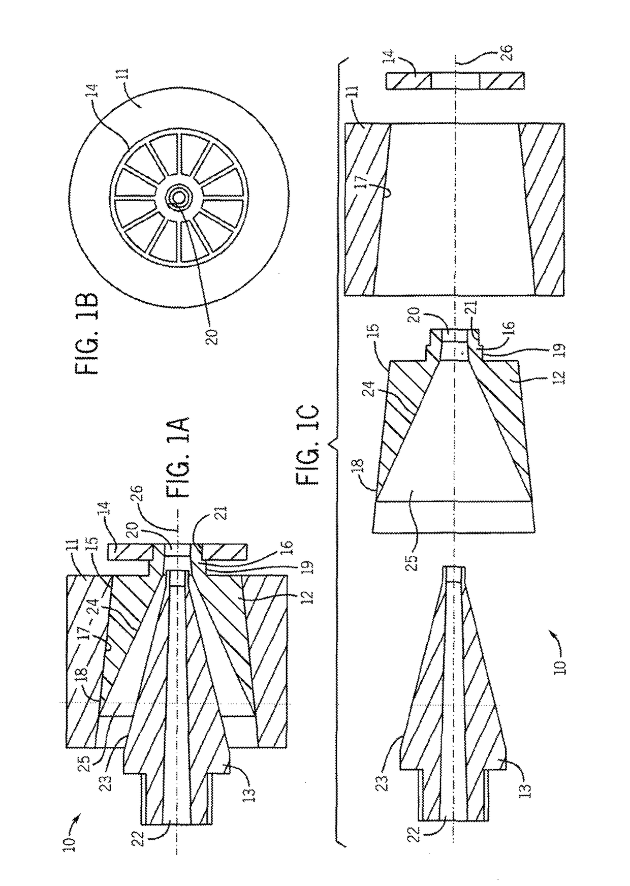
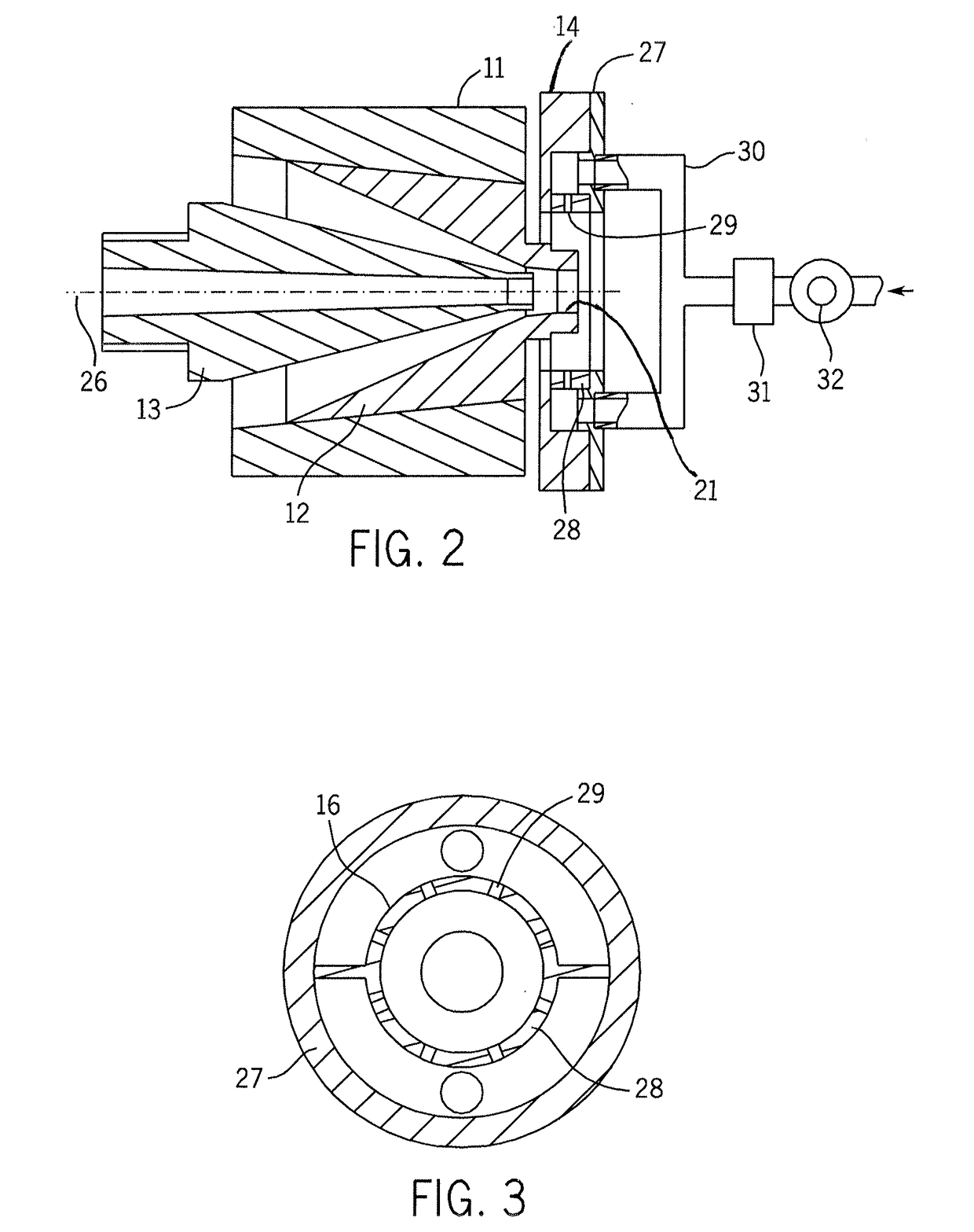
A die assembly (10) for extruding a polymeric coating onto a wire so as to impart a matte finish to the coating surface is provided. The die assembly (10) comprises: A) a die tip (13) comprising a tubular channel (22) through which a wire can pass, the channel (22) positioned along the central longitudinal axis (26) of the die assembly (10); B) a die body (12) comprising a trunk (15) and a head (16), the head (16) comprising a tubular channel (20), the head tubular channel (20) comprising a die land (21), the trunk (15) positioned about the die tip (13) so as to define an annular space (25) between the exterior surface (23) of the die tip (13) and the interior surface (24) of the trunk (15); C) a die holder (11) positioned about and in contact with the exterior surface (17) of the trunk (15); and D) a radiator (14) positioned about and in contact with the exterior surface (19) of the die land (21) of the die head (16).

Description

CROSS REFERENCE TO RELATED APPLICATION[0001]The present application is the national phase of PCT Patent Application No. PCT / CN2010 / 080515 filed Dec. 30, 2010, the entire content of which is incorporated by reference herein.BACKGROUND OF THE INVENTION[0002]1. Field of the Invention[0003]This invention relates to wire and cable coatings, particularly protective jackets. In one aspect the invention relates to wire and cable coatings with a matte finish while in another aspect, the invention relates to a die assembly with a cooled die land for imparting a matte finish to a polymeric wire and cable coating. In still another aspect the invention relates to a process of imparting a matte finish to a wire and cable coating without the use of inorganic additives or a change in coating formulation.[0004]2. Description of the Related Art[0005]For some electronic wires, such as power cords, USB cables, HDMI cables, mouse cables and the like, some manufacturers have cosmetic requirements that re...

Claims


Application Information

Patent Timeline
Patent Type & Authority Patents(United States)
IPC IPC(8): B29C47/02B29C47/86B29C47/28H01B13/14B29C47/00H01B7/00B29C48/06B29C48/34
CPCH01B13/14B29C47/0016B29C47/28H01B7/00B29C47/864B29C47/025B29C47/0014B29C48/06B29C48/34B29C48/87B29C48/05B29C48/154B29C48/30
Inventor YANG, YONGYONGBROWN, GEOFFREY D.MUNDRA, MANISHLI, BINZHU, JOURNEY LU
Owner DOW GLOBAL TECH LLC
Learn More