
Systems and methods for forming a layer onto a surface of a solid substrate and products formed thereby

a solid substrate and substrate technology, applied in the direction of brake discs, mechanical equipment, machines/engines, etc., can solve the problems of generating dust, rotor wear, and relatively heavy conventional cast iron brake rotors, and achieve the effects of improving mechanical and thermal properties, improving heat capacity, and improving wear ra

Inactive Publication Date: 2018-04-03
ATS MER LLC
View PDF8 Cites 82 Cited by
  • Summary
  • Abstract
  • Description
  • Claims
  • Application Information

AI Technical Summary

Benefits of technology

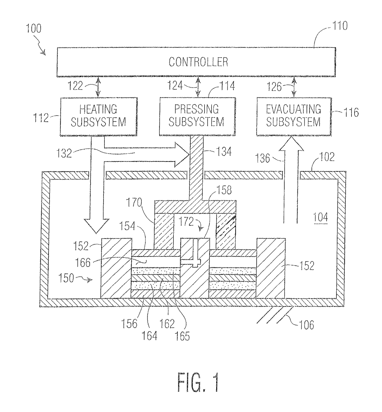
The present invention provides systems and methods for creating a composite layer on a substrate, such as a vehicular brake rotor, that is free of porosity and includes ceramic particles of desirable size and density. This composite layer provides better mechanical and thermal properties compared to the substrate without the layer. The composite layer can also be graded in density or volume of ceramic particles as a function of distance from the outer surface of the layer towards the substrate. Using a press and heating, cooling, or insulation, the process can be controlled to achieve desired results. The composite layer is made from ceramic particles in a metal matrix, which can withstand high temperatures encountered during vehicular braking. Aluminum, aluminum alloy, titanium, and titanium alloy are preferred substrates due to their lighter weight and high heat capacity.

Problems solved by technology

Conventional cast iron brake rotors are relatively heavy.
These rotors wear during braking, generating dust.
Reduced weight materials to cast iron include aluminum and titanium; however, their surface tribology in a friction application, in contrast to cast iron, lacks the necessary performance to function as a brake rotor.
Many conventional processes have drawbacks when applied to forming brake rotors with desirable features.
For example, some rotors formed of aluminum with a ceramic coating applied by a conventional plasma spray technique have unsatisfactory residual porosity as well as insufficient adhesion of the coating to the rotor substrate for vehicular rotor applications.
Conventional stir casting used to produce composites and particularly aluminum-ceramic particle composites inherently results in unacceptable porosity for most vehicular rotor applications.
Conventional stir casting is not known to produce pore free composites at this necessarily high particle loading.
A conventional stir process to incorporate fine ceramic particles into the aluminum matrix for brake rotor applications is limited to approximately 25% by volume, depending on the actual particle size, because slitting and casting of higher volume loading and viscosity mixtures become impractical.

Method used


Image

  • Systems and methods for forming a layer onto a surface of a solid substrate and products formed thereby
  • Systems and methods for forming a layer onto a surface of a solid substrate and products formed thereby
  • Systems and methods for forming a layer onto a surface of a solid substrate and products formed thereby

Examples


example i

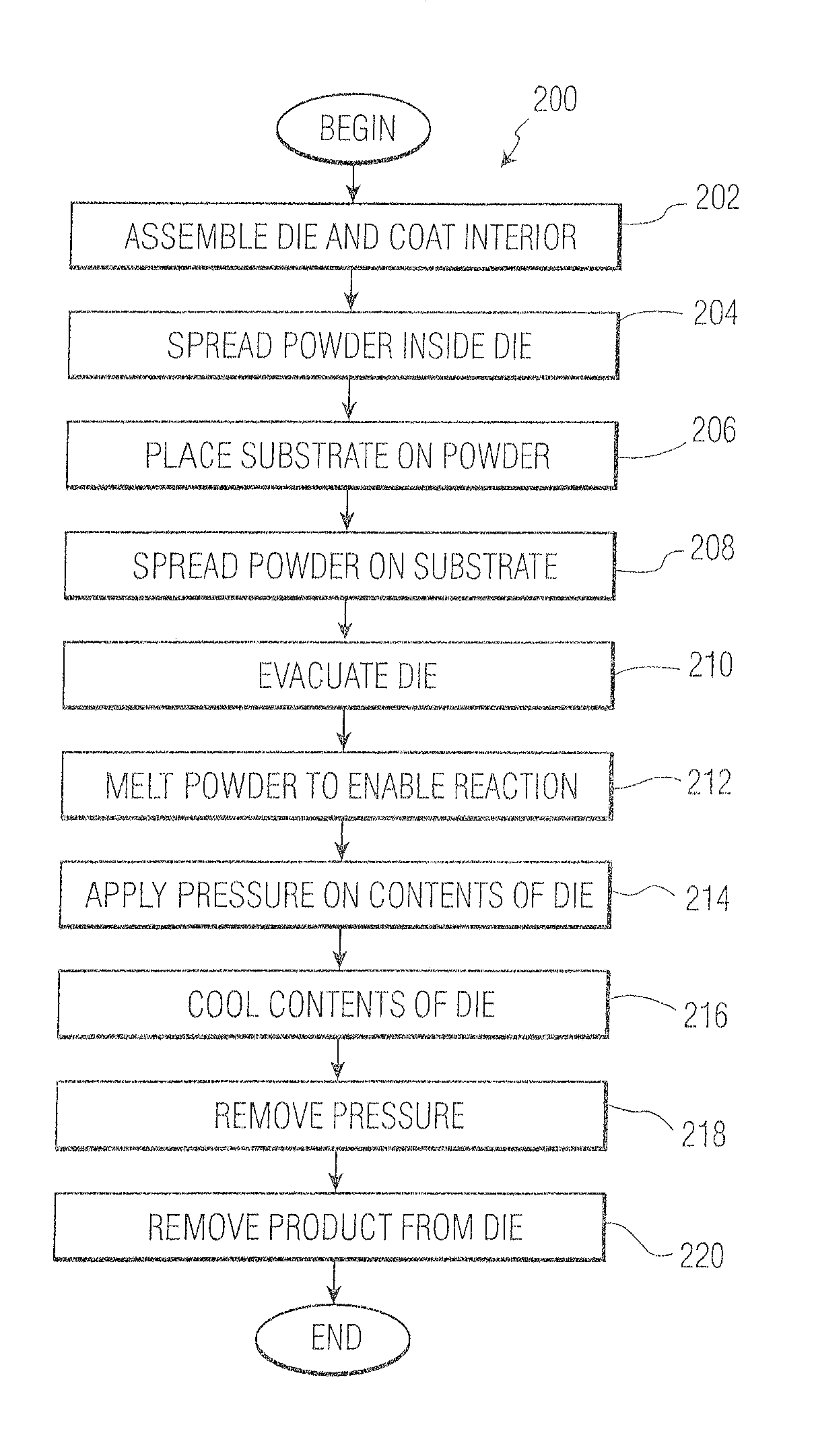
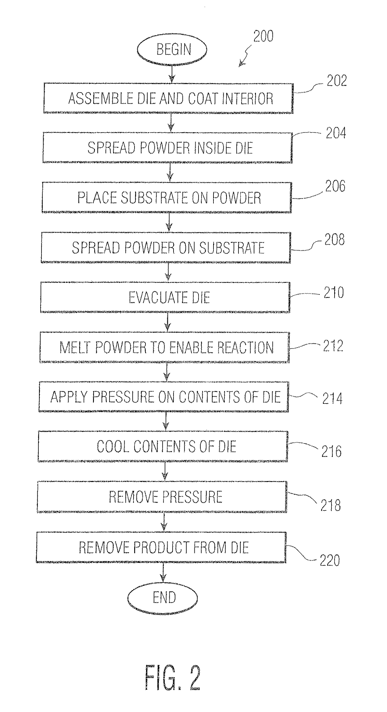
[0073]As a first example, a vehicular brake rotor may be formed using method 200 as follows. At steps 204 and 208 the powder comprises powdered aluminum silicon alloy, silicon carbide powder, and titanium powder. There is no binder in the powder. The AlSi alloy component material is 59.5% by weight of the type marketed by Valimet as Grade S-9 having a distribution of particle sizes defined by D10 4.82 microns, D50 15.23 microns, and D90 37.56 microns. The SiC component material is 38.0% by weight of the type marketed by ESK as Grade F600-D having particle size from 10 microns to 20 microns. The titanium component material is 2.5% by weight of the type marketed by ADMA having particle size of about 44 microns specified as 325-mesh. The powder is mixed until uniform in material distribution. Each powder portion 164 and 165 is spread to a uniform thickness of 0.010 inch to 0.25 inch, preferably 0.060 to 0.125 inch, more preferably 0.040 to 0.080 inch, most preferably about 0.050 inch.

[...

example ii

[0086]As a second example, a vehicular brake rotor may be formed in a variation of method 200 as follows. At steps 204 and 208, the powder comprises aluminum alloy, titanium, and silicon carbide. The aluminum alloy is of the type generally referred to as 356. Silicon carbide is included at 35% of the powder. Ninety percent of the silicon carbide particles are 15 micrometers (μm). The particles are dry mixed by any conventional mixing technology (e.g., ball mill with steel balls or ceramic balls, attrition milling, rotational tumbling, pulse fluid bed). After mixing to a uniform material consistency, the powder is poured into a die to contain the mixture when heated to above the melting point of the aluminum alloy of the powder.

[0087]At step 206, a plate of pure aluminum produced by casting or rolling is used as the substrate and aluminum alloy 356 used as the surface layers.

[0088]At step 210, the loaded die is placed in a chamber capable of evacuation of air. A vacuum pump is used t...

example iii

[0097]As a third example, the process of Example II was repeated, except the substrate was formed of aluminum alloy 5052, and the metal alloy powder used in the surface layers was type 4032.


PUM

PropertyMeasurementUnit
particle sizesaaaaaaaaaa
volume percentaaaaaaaaaa
porosityaaaaaaaaaa

Abstract

A method for forming a vehicular brake rotor involving loading a shaped metal substrate with a mixture of metal alloying components and ceramic particles in a dieheating the contents of the die while applying pressure to melt at least one of the metal components of the alloying mixture whereby to densify the contents of the die and form a ceramic particle-containing metal matrix composite coating on the metallic substrate; and cooling the resulting coated product.

Description

CROSS REFERENCE TO RELATED APPLICATIONS[0001]This application claims priority from U.S. Provisional Application Ser. No. 62 / 258,448, filed Nov. 21, 2015, and from US Provisional Application Ser. No. 62 / 265,765, filed Dec. 10, 2015, the contents of which are incorporated herein by reference.FIELD OF THE INVENTION[0002]The present invention relates to the formation of substantially pore free wear resistant metal ceramic particulate composites on metal substrates, systems for forming such composite layers, and products made. The invention has particular utility in connection with vehicular brake rotors and will be described in connection with such utility, although other utilities are contemplated.BACKGROUND OF THE INVENTION[0003]Land vehicles including cars, trucks, trains, and mass transit systems use disc brakes to slow and / or stop the vehicle. Disc brake systems generally include a rotor and caliper. The rotor is mounted to turn with the wheel of the vehicle. The caliper includes b...

Claims


Application Information

Patent Timeline
Patent Type & Authority Patents(United States)
IPC IPC(8): F16D65/12B22D19/08B22D23/06B22D27/15
CPCF16D65/127B22D19/08B22D23/06F16D65/125B22D27/15F16D2200/0086F16D2200/003B22F7/04B22F2007/045B32B15/01C22C1/0416C22C19/05C22C32/0063C23C24/103F01D5/28
Inventor BRACAMONTE, LORIWITHERS, JAMESABCEDE, JOWIE
Owner ATS MER LLC
Learn More