Scintillation event position determination in a radiation particle detector

a radiation particle and event position technology, applied in the field of radiation particle detectors, can solve the problems of deteriorating scintillation event localization and inaccurate threat logic, and achieve the effects of reducing the dead time of the photosensor, improving the localization performance of scintillation event, and low scintillation event ra

Active Publication Date: 2018-02-27
KONINKLJIJKE PHILIPS NV
View PDF11 Cites 4 Cited by
  • Summary
  • Abstract
  • Description
  • Claims
  • Application Information

AI Technical Summary

Benefits of technology

[0037]Preferably, the reference photon distribution and/or the triggering probability for each of the photosensors is determined based on measurements acquired during a calibration procedure. The calibration measurement may be carried out in advance of detecting radiation with the radiation detector. Advantageously, the calibration measurement is carried out at low scintillation event rates in order to reduce dead time of the photosensors as much as possible.
[0038]According to another preferred embodiment of the present invention, the step of determining the triggering probability of one of the photosensors includes determining, in particular measuring, a mean triggering probability of said photosensor. Determining a mean triggering probability and using this mean probability to calculate the likelihood for each of the scintillator element locations allows an improvement of scintillation event localization performance with reduced effort. It is merely required to store a single constant probability value for each of the photosensors. For example, the triggering probability of a photosensor that is not functional can be set to zero, whereas the triggering probability of a functional photosensor can be set to a constant value greater than zero.
[0039]According to another preferred embodiment of the present invention, the step of determining the triggering probability of one of the photosensors includes determining a dependence of the triggering probability on the number of photons incident on said photosensor. Thus, it is possible to calculate the likelihood of each of the scintillator element locations based on a triggering probability that is a function of the number of incident photons, thereby further

Problems solved by technology

Since Anger logic relies on information from neighboring photosensors to identify the scintillator element location, Anger logic becomes inaccurate when information of some of the photosensors is missing, e.g. due to the scintillation event happening during a

Method used


Image

  • Scintillation event position determination in a radiation particle detector
  • Scintillation event position determination in a radiation particle detector
  • Scintillation event position determination in a radiation particle detector

Examples


first embodiment

[0051]FIG. 1 illustrates a radiation particle detector 1 employed in a nuclear imaging system, e.g. a high-resolution PET scanner. The radiation particle detector 1 comprises a pixellated scintillator with a plurality of scintillator element locations, wherein the scintillator element locations are scintillator elements 2. The material of the scintillator elements 2 is selected to provide a high stopping power for 511 keV gamma rays with rapid temporal decay of the scintillation burst. Some suitable scintillator materials are lutetium oxyorthosilicate (LSO), lutetium yttrium orthosilicate (LYSO) and lanthanum bromide (LaBr). It should be appreciated that scintillator elements 2 made of other materials can be used instead. The structure of the scintillator material may for example be crystalline, polycrystalline, or ceramic. The scintillator elements 2 are arranged in a scintillator layer 3. In order to avoid light sharing between the scintillator elements 2 a reflector material 4, e...

second embodiment

[0065]The radiation particle detector does not comprise a light guide. Nevertheless, a light guide can optionally be disposed between the scintillator layer 3 and the photosensor layer 6 to further enhance light spreading onto the photosensors 5.1, 5.2, 5.3, 5.4.

[0066]FIG. 2 illustrates an interaction of gammy ray 10 with the monolithic scintillator 2 of the scintillator layer 3. Gamma ray 10 is stopped at a scintillator element location and the resulting burst of photons is spread over three neighboring photosensors 5.1, 5.2, 5.3.

[0067]The position as well as the energy of a scintillation event in the radiation particle detector according to the second embodiment may be determined as described with reference to the first embodiment.

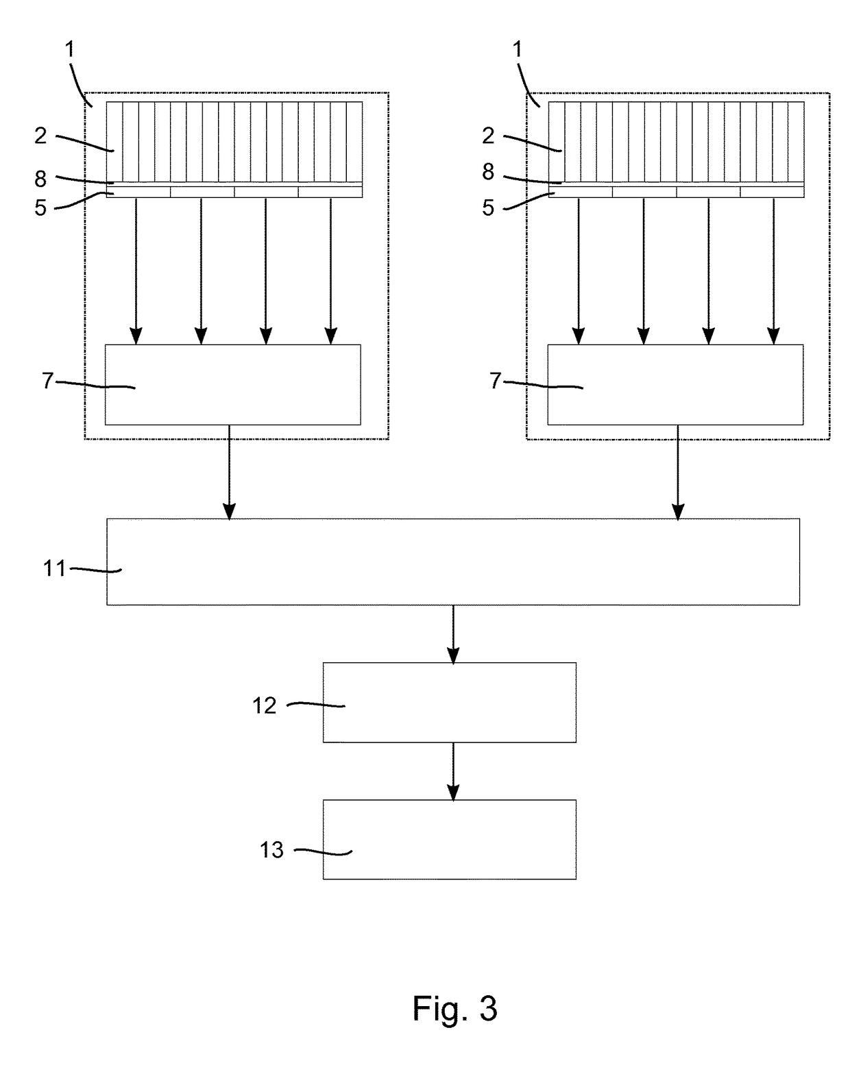
[0068]FIG. 3 is a diagrammatic illustration of a nuclear imaging system configured as a PET scanner including a plurality of radiation particle detectors 1. The radiation particle detectors 1 are arranged in one or more rings along an axial direction; h...


PUM


Abstract

A method for determining the position of a scintillation event in a radiation particle detector with multiple scintillator element locations which are configured to emit a burst of photons responsive to a radiation particle being absorbed at the scintillator element location and with a plurality of photosensors (5.1, 5.2, 5.3, 5.4) optically coupled to said scintillator element locations, comprising the steps of determining, for each of the photosensors (5.1, 5.2, 5.3, 5.4), a triggering probability indicative of the probability of said photosensor (5.1, 5.2, 5.3, 5.4) measuring a number of photons that exceeds a predetermined triggering threshold; measuring a photon distribution with the photosensors (5.1, 5.2, 5.3, 5.4) indicative of the number of photons incident on the individual photosensors (5.1, 5.2, 5.3, 5.4); calculating, for each of the scintillator element locations, a likelihood that a scintillation event with a predetermined energy value took place in said scintillator element location based on the measured photon distribution and the triggering probability of each of the photosensors (5.1, 5.2, 5.3, 5.4); and identifying the scintillator element location having the maximum likelihood.

Description

CROSS REFERENCE TO RELATED APPLICATIONS[0001]This application is the U.S. National Phase application under 35 U.S.C. § 371 of International Application No. PCT / EP2016 / 054485, filed Mar. 3, 2016, published as WO 2016 / 146391 on Sep. 22, 2016, which claims the benefit of European Patent Application Number 15159419.9 filed Mar. 17, 2015. These applications are hereby incorporated by reference herein.FIELD OF THE INVENTION[0002]The present invention relates to the field of radiation particle detectors. It finds particular application in nuclear imaging systems such as, for example positron emission tomography (PET) scanners for clinical or research studies as well as single photon emission computed tomography (SPECT) scanners.BACKGROUND OF THE INVENTION[0003]In PET scanners pixellated scintillator elements are typically used to convert incident radiation particles to bursts of photons with a wavelength in the UV or visible spectrum. The scintillator elements are typically arranged in a m...

Claims


Application Information

Patent Timeline
IPC IPC(8): G01T1/20G01T1/164G01T1/24G01R33/48G01T1/16G01T1/29
CPCG01T1/2985G01T1/1647G01T1/20G01T1/243G01R33/481G01T1/1603G01T1/1642
Inventor BERKER, YANNICKSCHULZ, VOLKMAR
Owner KONINKLJIJKE PHILIPS NV
Why Eureka
Try Eureka