
Switch driving circuit and switch driving method

a driving circuit and switch technology, applied in the direction of electric variable regulation, process and machine control, instruments, etc., can solve the problems of easy breakage increased power loss of the switching element, and hard switching, so as to prevent the damage to the switching element due to hard switching

Active Publication Date: 2014-05-27
SEMICON COMPONENTS IND LLC
View PDF7 Cites 14 Cited by
  • Summary
  • Abstract
  • Description
  • Claims
  • Application Information

AI Technical Summary

Benefits of technology

[0008]The present invention provides a switch driving circuit and a driving method thereof that are capable of preventing the hard switching.
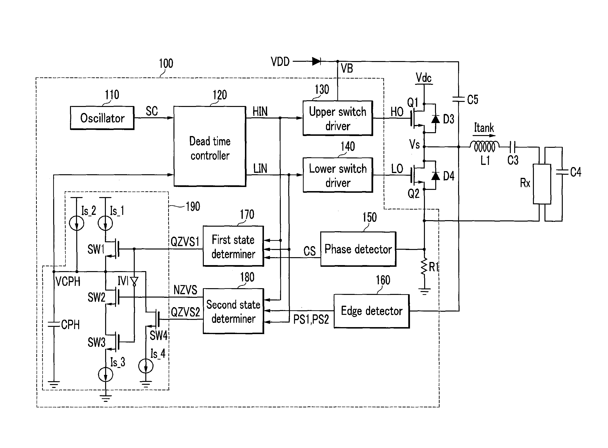
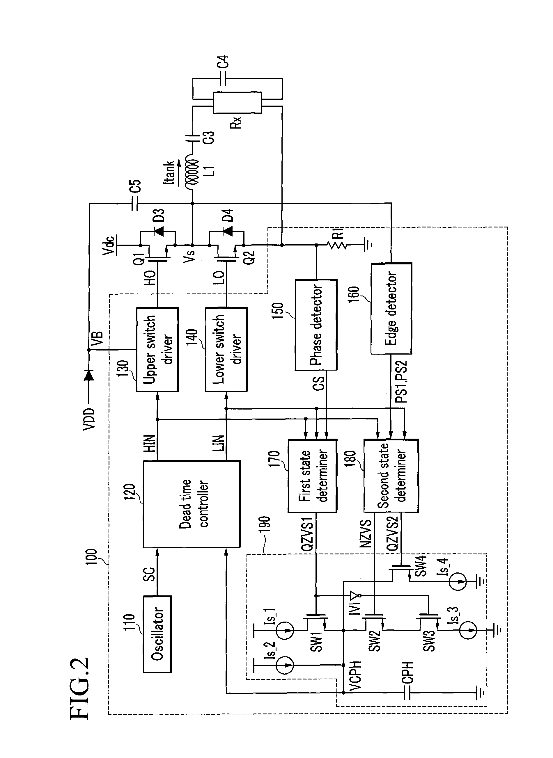
[0011]The switch driving circuit further includes a first state determiner receiving the phase information signal, the high-side switch driver controlling signal, and the low-side switch driver controlling signal input to compare the turn-on time of the high-side switch and the turn-on time of the low-side switch, and the corresponding phase changing time of the resonance current, and generating a first quasi-zero voltage switching signal to reduce the dead time if the turn-on time of the high-side switch and the turn-on time of the low-side switch are later than the corresponding phase changing time.
[0028]As described above, according to the present invention, the damage to the switching element due to the hard switching may be prevented.

Problems solved by technology

Thus, hard switching is generated.
Generally, if the hard switching is generated, the power loss of the switching element is increased, and the switching element is easily broken.

Method used


Image

  • Switch driving circuit and switch driving method
  • Switch driving circuit and switch driving method
  • Switch driving circuit and switch driving method

Examples


Embodiment Construction

[0034]In the following detailed description, only certain exemplary embodiments of the present invention have been shown and described, simply by way of illustration. As those skilled in the art would realize, the described embodiments may be modified in various different ways, all without departing from the spirit or scope of the present invention. Accordingly, the drawings and description are to be regarded as illustrative in nature and not restrictive. Like reference numerals designate like elements throughout the specification.

[0035]Throughout this specification and the claims that follow, when it is described that an element is “coupled” to another element, the element may be “directly coupled” to the other element or “electrically coupled” to the other element through a third element. In addition, unless explicitly described to the contrary, the word “comprise” and variations such as “comprises” or “comprising” will be understood to imply the inclusion of stated elements but n...


PUM


Abstract

The present invention relates to a switch driving circuit and a driving method thereof that are capable of preventing hard switching. The present invention includes: a dead time controller generating an high-side switching driver controlling signal and a low-side switching driver controlling signal controlling the switching operation of the high-side switch and the low-side switch according to a dead time controlling signal; and a phase detector detecting a phase of a resonance current flowing into the second power voltage terminal to generate a phase information signal, wherein one of the high-side switch driver controlling signal and a signal corresponding thereto, and the phase information signal are compared, and if the turn-on time of the high-side switch is later than the phase change of the resonance current, the dead time is controlled for the turn-on time of the high-side switch to advance the phase change of the resonance current.

Description

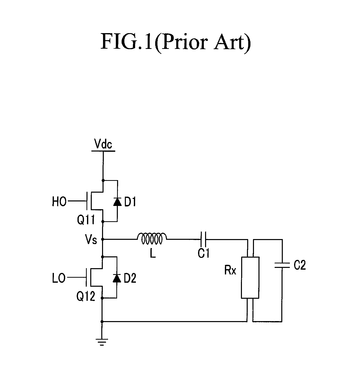
CROSS-REFERENCE TO RELATED APPLICATION[0001]This application claims priority to and the benefit of Korean Patent Application No. 10-2010-0016766 filed in the Korean Intellectual Property Office on Feb. 24, 2010, the entire contents of which are incorporated herein by reference.BACKGROUND OF THE INVENTION[0002](a) Field of the Invention[0003]The present invention relates to a switch driving circuit and a switch driving method.[0004](b) Description of the Related Art[0005]FIG. 1 is a schematic view of a circuit generating AC power through a switching operation of a conventional switch and supplying it to a load. An high-side switch Q11 and a low-side switch Q12 shown in FIG. 1 include an n-channel MOSFET. The drain electrode of the high-side switch Q11 is input with a predetermined power voltage Vdc, and the gate electrode is input with a gate signal HO. The drain electrode of the low-side switch Q12 is connected to a source electrode of the high-side switch Q11, and the source electr...

Claims


Application Information

Patent Timeline
Patent Type & Authority Patents(United States)
IPC IPC(8): H02M7/539
CPCY02B70/1441H02M2007/4815H02M7/53803Y02B70/10H02M7/4815G05F3/06H02M3/3353H02M3/337
Inventor CHO, GYE-HYUNBAEK, IN-KUK
Owner SEMICON COMPONENTS IND LLC
Learn More