
Electroacoustic converter film, flexible display, vocal cord microphone, and musical instrument sensor

a converter film and flexible technology, applied in the direction of instrument details, device material selection, piezoelectric/electrostrictive devices, etc., can solve the problems of constant and external bending deformation, and consequent bending stress, and achieve excellent flexibility and acoustic characteristics, stable sound output, and no impairment of lightweightness or flexibility

Active Publication Date: 2017-09-12
FUJIFILM CORP
View PDF35 Cites 11 Cited by
  • Summary
  • Abstract
  • Description
  • Claims
  • Application Information

AI Technical Summary

Benefits of technology

The present invention is aimed at providing an electroacoustic converter film that can be used as a flexible speaker and can be integrated with a flexible display without impairing its lightweightness or flexibility. The film should have excellent flexibility and acoustic characteristics, and should be able to output sound stably even if deformed. Additionally, the invention also provides a flexible display, a vocal cord microphone, and a musical instrument sensor that use the electroacoustic converter film as a sensor. These should have small and simple configurations, and should be able to stably reproduce voice and sound of musical instruments with high fidelity regardless of the bending direction or the place where they are used.

Problems solved by technology

For example, when a flexible display is gripped in a gently bent manner just like documents such as a newspaper or a magazine as a portable apparatus, the display constantly and externally experiences severe bending deformation which is caused relatively slow at a frequency of several Hz or lower.
At this time, if the polymeric composite piezoelectric body is hard, great bending stress is caused accordingly.
Consequently, cracks may occur at the interface between the polymer matrix and the piezoelectric particles, leading to breakage.

Method used


Image

  • Electroacoustic converter film, flexible display, vocal cord microphone, and musical instrument sensor
  • Electroacoustic converter film, flexible display, vocal cord microphone, and musical instrument sensor
  • Electroacoustic converter film, flexible display, vocal cord microphone, and musical instrument sensor

Examples


example 1

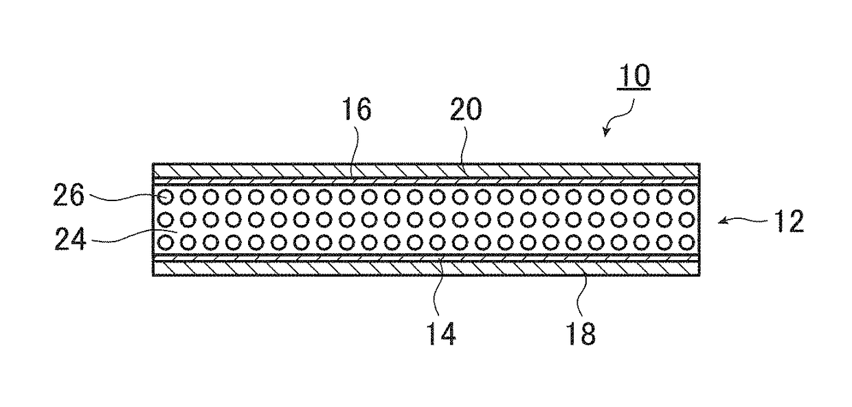
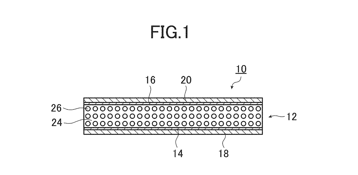
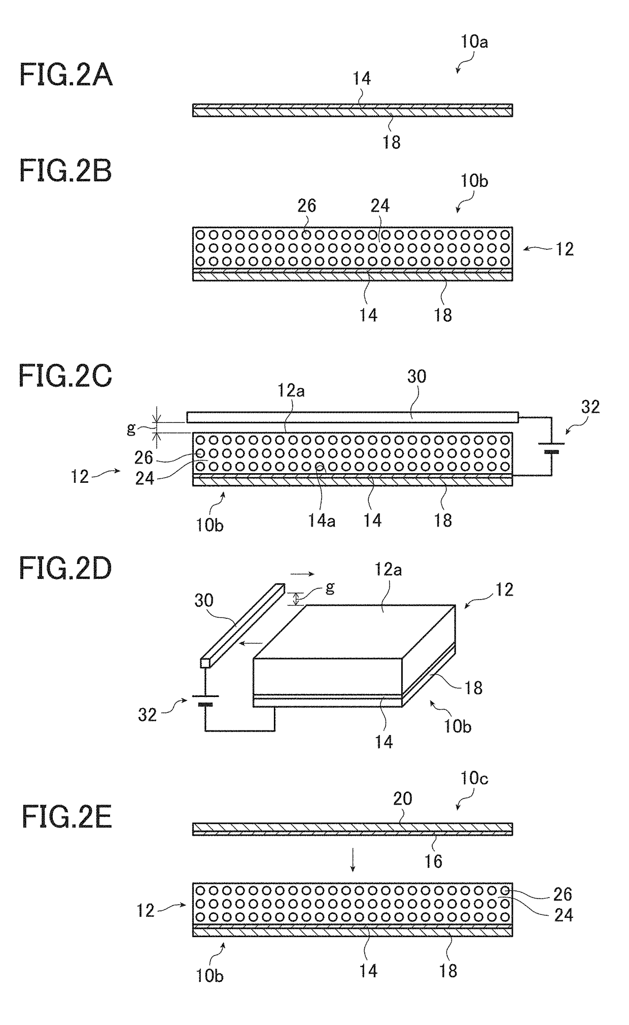
[0259]By the method as described above and illustrated in FIG. 2, the converter film 10 of the present invention shown in FIG. 1 was prepared.

[0260]First, according to the compositional ratio as below, cyanoethylated PVA (CR-V manufactured by Shin-Etsu Chemical Co., Ltd.) was dissolved in dimethylformamide (DMF). To the resultant solution, PZT particles were added at the compositional ratio below, and dispersed by a propeller mixer (rotation frequency of 2,000 rpm), thereby preparing a coating material for forming the piezoelectric body layer 12.

[0261]

PZT particles300 parts by weight Cyanoethylated PVA30 parts by weightDMF70 parts by weight

[0262]The PZT particles used were prepared by sintering commercially available PZT raw material powder at 1,000 to 1,200° C. and then performing crushing and classification treatment on the sintered material so as to obtain the particles having an average particle size of 5 μm.

[0263]Meanwhile, the sheet-like substances 10a and 10c were prepared by...

example 2

[0301]The converter film 10 was prepared in the completely same manner as in Example 1, except that the sheet-like substances 10a and 10c as used were each obtained by vacuum-depositing a thin copper film having a thickness of 0.1 μm onto a PET film having a thickness of 12 μm.

[0302]That is, in this example, the thin film electrodes 14 and 16 are each composed of the deposited thin copper film having a thickness of 0.1 μm, and the protective layers 18 and 20 are each composed of the PET film having a thickness of 12 μm. The thickness of the piezoelectric body layer 12 was 45 μm.

[0303]Regarding the converter film 10 prepared in this manner, the flexibility test, dynamic viscoelasticity test and speaker performance test were performed in the same manner as in Example 1.

[0304]The results of the flexibility test are shown in Table 1, the temperature dependence of the dynamic viscoelasticity at 1 Hz is shown in FIG. 13A and Table 1, and the measurement results of the sound pressure level...

example 3

[0305]The converter film 10 was prepared in the completely same manner as in Example 1, except that the sheet-like substances 10a and 10c as used were each obtained by vacuum-depositing a thin copper film having a thickness of 0.1 μm onto a PET film having a thickness of 25 μm. That is, in this example, the thin film electrodes 14 and 16 are each composed of the deposited thin copper film having a thickness of 0.1 μm, and the protective layers 18 and 20 are each composed of the PET film having a thickness of 25 μm.

[0306]Regarding the converter film 10 prepared in this manner, the flexibility test, dynamic viscoelasticity test and speaker performance test were performed in the same manner as in Example 1.

[0307]The results of the flexibility test are shown in Table 1, the temperature dependence of the dynamic viscoelasticity at 1 Hz is shown in FIG. 13A and Table 1, and the measurement results of the sound pressure level-frequency characteristics are shown in FIG. 10. The temperature ...


PUM

PropertyMeasurementUnit
frequencyaaaaaaaaaa
glass transition temperatureaaaaaaaaaa
temperatureaaaaaaaaaa

Abstract

Provided is an electroacoustic converter film including: a polymeric composite piezoelectric body having piezoelectric particles dispersed in a viscoelastic matrix which is formed of a polymer material exhibiting viscoelasticity at ordinary temperatures; thin film electrodes formed on both sides of the polymeric composite piezoelectric body; and protective layers formed on surfaces of the thin film electrodes. The electroacoustic converter film serves as a speaker capable of being integrated with a flexible display without impairing lightweightness or flexibility, and has considerable frequency dispersion in the storage modulus and also has a local maximum of the loss tangent around ordinary temperatures. A flexible display, a vocal cord microphone and a musical instrument sensor, in each of which the electroacoustic converter film is used, are also provided.

Description

CROSS REFERENCE TO RELATED APPLICATIONS[0001]This application is a continuation application of International Application PCT / JP2012 / 075392 filed on Oct. 1, 2012, which claims priority under 35 U.S.C. 119(a) to Application No. 2011-218499 filed in Japan on Sep. 30, 2011 and Application No. 2012-129965 filed in Japan on Jun. 7, 2012, all of which are hereby expressly incorporated by reference into the present application.BACKGROUND OF THE INVENTION[0002]The present invention relates to an electroacoustic converter film used for acoustic devices such as speakers or microphones. More specifically, the present invention relates to an electroacoustic converter film which has excellent flexibility and acoustic characteristics, can stably output sound even if deformed, and makes it possible to realize a flexible speaker or the like suitably usable for a flexible display or the like. The present invention also relates to a flexible display, a vocal cord microphone and a musical instrument se...

Claims


Application Information

Patent Timeline
Patent Type & Authority Patents(United States)
IPC IPC(8): H01L41/04H01L41/18G10H3/14H04R17/00H01L41/08H04R7/04H04R1/46H04R31/00G02F1/1333
CPCH01L41/0805G10H3/143G10H3/146H04R7/04H04R17/005G02F2001/133394G10H2220/531G10H2220/545G10H2220/551H04R1/46H04R31/003H04R2307/025H04R2499/15G02F1/133394H10N30/852H10N30/045H10N30/704
Inventor MIYOSHI, TETSU
Owner FUJIFILM CORP
Learn More