
Thin film transistor

a thin film transistor and film technology, applied in the field of thin film transistors, can solve the problems of poor heat resistance of the resin substrate, deterioration of the reliability of the display device itself, image irregularities and/or tft characteristics, etc., and achieve excellent stress resistance, small threshold voltage shift, and high mobility of 40 cm2/vs

Inactive Publication Date: 2017-05-02
KOBE STEEL LTD
View PDF27 Cites 1 Cited by
  • Summary
  • Abstract
  • Description
  • Claims
  • Application Information

AI Technical Summary

Benefits of technology

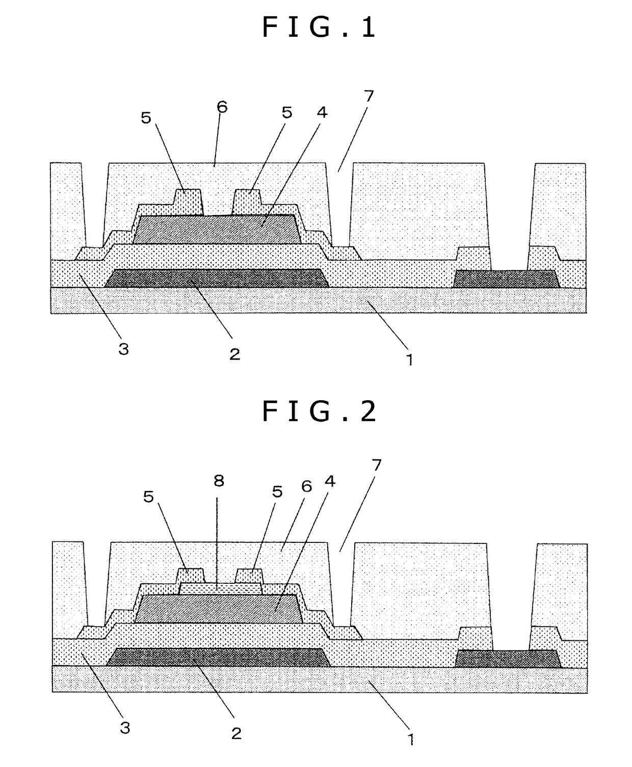
[0038]The present invention can provide a BCE TFT including no etch stopper layer, where the TFT includes a semiconductor layer derived from an oxide as follows. The oxide has an extremely high mobility of 40 cm2 / Vs or more and offers excellent stress resistance (has a small shift in threshold voltage between before and after the application of light and / or negative bias). In addition, the oxide has (A) excellent solubility (wet etching characteristics) in a wet etchant for oxide semiconductor processing and has (B) excellent durability in etching via wet etching using a wet etchant for source-drain electrodes or via dry etching, and still has excellent resistance to a resist stripper used in photolithography. Namely, the oxide has (B) excellent durability in etching and excellent resistance to photoresist stripper.
[0039]The present invention can also provide an ESL TFT including an etch stopper layer, where the TFT includes a semiconductor layer derived from an oxide as follows. The oxide has an extremely high mobility of 40 cm2 / Vs or more and contributes to excellent switching behavior and stress resistance of the TFT. In addition, the oxide has excellent adaptability to wet etching process, namely, the oxide has (A) excellent solubility (wet etching characteristics) in a wet etchant for oxide semiconductor processing.

Problems solved by technology

The oxide semiconductors are therefore expected to be applied typically to next-generation displays and to resin substrates, where the next-generation displays require large sizes, high resolutions, and high-speed drive, and the resin substrates have poor heat resistance.
This light applies stress to the TFT and causes image irregularities and / or deterioration in TFT characteristics.
Upon actual use of the TFT, the change in switching behavior caused by stress due to the application of light or voltage causes deterioration in reliability of the display device itself.
Likewise, organic electroluminescent displays disadvantageously suffer from variations in values typically of threshold voltage, because light leaked out from the light-emitting layer is applied to the semiconductor layer.
As is described above, strong demands are made to improve stress resistance, because the threshold voltage shift, in particular, causes deterioration in reliability of display devices including TFTs.
In this process, the thin oxide semiconductor film is required to resist erosion and damage by the wet etchant on the surface (back channel) side of the thin oxide semiconductor film, where the erosion and damage may cause deterioration in TFT characteristics and stress resistance.
Specifically, the IGZO is excellent in the property (A), i.e., wet etching characteristics upon thin oxide semiconductor film processing, but is inferior in the property (B1), i.e., durability in wet etching upon source-drain electrodes processing.
Disadvantageously, the IGZO film may disappear upon source-drain electrodes processing with the wet etchant to impede the TFT formation or may cause the resulting TFT to have TFT characteristics and other properties at inferior levels.
However, this chemical (wet etchant) has a short lifetime, is unstable, and offers poor mass productivity.
However, the above-described disadvantages of the BCE TFT in wet etching are highly feared.
Certainly, the ESL TFT illustrated in FIG. 2 may also suffer from the disadvantages caused by wet etchants of some types.
The disadvantages have been described in the property (B1) in the case where the source-drain electrodes are etched via wet etching with a wet etchant.
The same disadvantages also occur in the case where the source-chain electrodes are etched via dry etching.
In this process, the disadvantages also occur when a resist stripper is used for resist removal and / or for cleaning.
The formation of the sacrificial layer or cutout, however, requires a larger number of steps.
However, it is difficult to uniformly remove the damaged layer.

Method used


Image

  • Thin film transistor
  • Thin film transistor
  • Thin film transistor

Examples


experimental example 1

ESL TFT

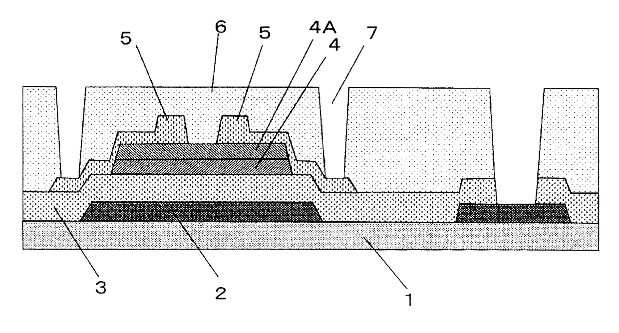
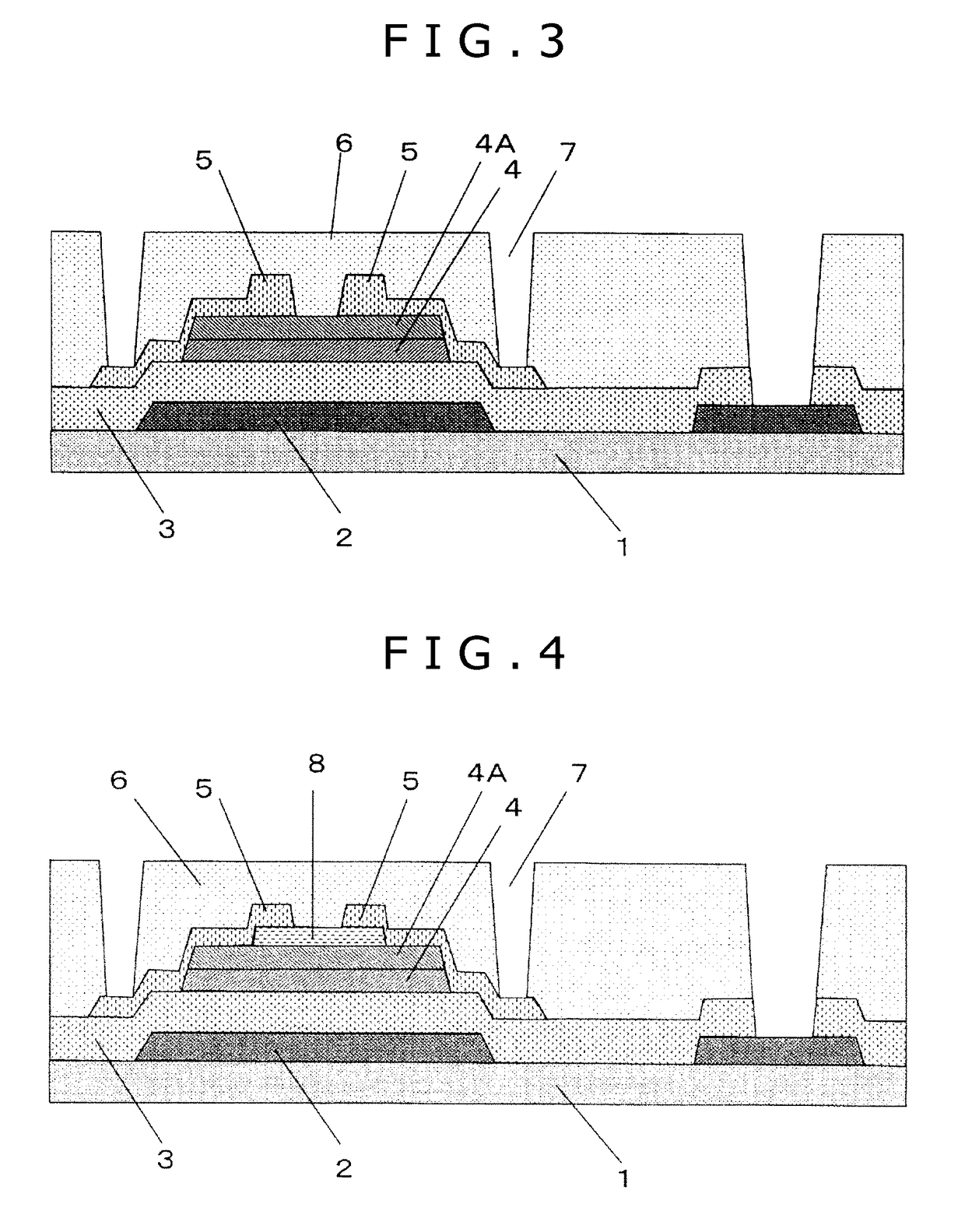
[0150]In this experimental example, ESL TFTs (FIG. 4) including oxide semiconductor layers of various types were produced and were evaluated on characteristics.

[0151]First oxide semiconductor layers were formed in this experimental example using two different IGZTOs, i.e., IGZTO “A” and IGZTO “B” given in Table 1. These IGZTOs are both examples having metal element ratios meeting the conditions specified in the present invention.

[0152]Second oxide semiconductor layers were formed in this experimental examples using a total of eleven (11) different IGZTOs, i.e., IGZTOs “a” to “k” given in Table 2. Among them, the IGZTOs “a” to “c” and “k” are examples having metal element ratios meeting the conditions specified in the present invention, and the IGZTOs “d” to “j” are examples having metal element ratios not meeting one or more of the conditions specified in the present invention.

[0153]Initially, a molybdenum (Mo) thin film having a thickness of 100 nm as a gate electrode 2 and ...

experimental example 2

BCE TFT

[0231]In this experimental example, the etching rate of each oxide semiconductor layer by a resist stripper was measured to evaluate resistance to resist stripper. For simplified measurement, the oxide semiconductor layer was deposited not to have a multilayer structure, but to have a single layer structure of a first oxide semiconductor layer alone. The etching rate was measured in a manner as follows.

[0232]Two different IGZTOs “A” and “B” in Table 6 were used to form the first oxide semiconductor layer. These are oxides meeting conditions in metal element ratios specified in the present invention and are the same as the IGZTOs “A” and “B” in Table 1. For comparison, an IGZO “C” (including no Sn, having an atomic ratio of In:Ga:Zn of 1:1:1) as given in Table 6 was used to form the first oxide semiconductor layer.

[0233]

TABLE 6First oxide semiconductorGa / Ga / (In + Sn / (In + Sym-(In + Ga + Zn + Ga + Zn +bolInGaZnSnGa)Sn)Sn)A174033100.700.400.15B171747190.500.320.19C33.333.333.300...

experimental example 3

BCE TFT

[0252]In this experimental example, BCE TFTs including various oxide semiconductor layers were produced and evaluated on characteristics. This experimental example employed the oxides “A” to “C” in Table 7 to form the first oxide semiconductor layer and the oxide IGTO “a” in Table 2 to form the second oxide semiconductor. The source-drain electrodes were etched herein using a wet etchant.

[0253]Initially, a molybdenum (Mo) thin film having a thickness of 100 nm as a gate electrode 2, and a SiO2 film having a thickness of 250 nm as a gate insulator film 3 were sequentially deposited on or over a glass substrate 1 (Corning's EAGLE XG, 100 mm in diameter by 0.7 mm in thickness). The gate electrode 2 was deposited by direct-current sputtering using a pure molybdenum (Mo) sputtering target at a deposition temperature of room temperature, a deposition power of 300 W, with a carrier gas of Ar, and at a gas pressure of 2 mTorr. The gate insulator film 3 was deposited by plasma CVD, wi...


PUM

PropertyMeasurementUnit
thicknessaaaaaaaaaa
threshold voltageaaaaaaaaaa
thicknessaaaaaaaaaa

Abstract

Provided is a thin film transistor that has high mobility and excellent stress resistance and is good typically in adaptability to wet etching process. The thin film transistor includes a substrate, and, disposed on the substrate in the following sequence, a gate electrode, a gate insulator film, oxide semiconductor layers, source-drain electrodes, and a passivation film that protects the source-drain electrodes. The oxide semiconductor layers have a first oxide semiconductor layer including In, Ga, Zn, Sn, and O, and a second oxide semiconductor layer including In, Ga, Sn, and O. The second oxide semiconductor layer is disposed on the gate insulator film. The first oxide semiconductor layer is disposed between the second oxide semiconductor layer and the passivation film. The atomic ratios in contents of the individual metal elements to all the metal elements constituting the first and the second oxide semiconductor layers are controlled to predetermined ratios.

Description

TECHNICAL FIELD[0001]The present invention relates to thin film transistors (TFTs), which are used for display devices such as liquid crystal displays (LCDs) and organic electroluminescent displays.BACKGROUND ART[0002]Oxide semiconductors have higher mobility and larger optical band gaps, and can be deposited at lower temperatures, as compared with general amorphous silicon (a-Si). The oxide semiconductors are therefore expected to be applied typically to next-generation displays and to resin substrates, where the next-generation displays require large sizes, high resolutions, and high-speed drive, and the resin substrates have poor heat resistance. For example, an IGZO semiconductor is generally used as the oxide semiconductor. The IGZO semiconductor refers to an amorphous oxide semiconductor including indium, gallium, zinc, and oxygen (In—Ga—Zn—O) (Patent Literature 1).[0003]Demands for still higher mobility have been made more and more on such oxide semiconductors. For example, a...

Claims


Application Information

Patent Timeline
Patent Type & Authority Patents(United States)
IPC IPC(8): H01L29/10H01L29/417H01L29/786H01L27/12G02F1/1368
CPCH01L27/1225G02F1/1368H01L29/41733H01L29/786H01L29/7869H01L29/78618H01L29/78696H01L29/66969H01L21/306H01L29/78606
Inventor GOTO, HIROSHIMIKI, AYAOCHI, MOTOTAKA
Owner KOBE STEEL LTD
Learn More